
The Renault Master belongs to the light commercial vehicle (LCV) range. Over the years, it has been offered in various body styles, including standard and extended-wheelbase variants. Heavy-duty Master variants with higher payloads are also marketed under the Messenger and Mascott names. This model is twin-badged with the Opel Movano and Nissan Interstar, sharing an identical fuse and relay layout. The third generation was produced from 2010 through the present. Below is detailed information on the location, layout diagrams, and photographs of the fuse and relay boxes for the third-generation Renault Master (chassis codes FV, JV; X62 platform). The fuse for the “cigarette lighter” is highlighted in bold.
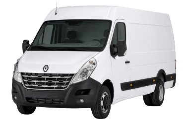
Because the Renault Master was manufactured over an extended period with various body configurations and electrical options, a single universal fuse and relay diagram cannot apply to all models. Please exercise caution, as the manufacturer reserves the right to make technical design changes without prior notice. Your vehicle’s actual fuse box layout may differ from the information presented here. For specific queries, contact an authorized dealer.
Engine Compartment
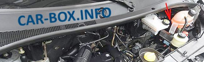
The fuse box is located on the right-hand side of the engine compartment, behind the coolant expansion tank.
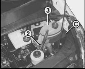
To access the box, loosen screw (2) and set aside the coolant expansion tank (3).

Then remove the four screws (4) and invert fuse box (5).
Type 1

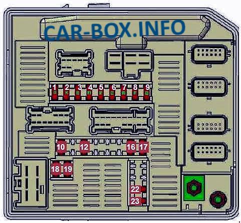
Overview.
| Diagram | |
|---|---|
|
|
| No. | Rating / Description |
| F1 | 7.5 A – Right-hand side marker light |
| F2 | 7.5 A – Left-hand side marker light |
| F3 | 10 A – Right low-beam headlamp |
| F4 | 10 A – Left low-beam headlamp |
| F5 | 20 A – Front fog lights |
| F6 | 10 A – Left high-beam headlamp |
| F7 | 10 A – Right high-beam headlamp |
| F8 | 25 A – ABS ECU power supply |
| F9 | 30 A – Windshield wiper system |
| F10 | 10 A – Airbag ECU (ignition supply) |
| F11 | Not used |
| F12 | 20 A – Transmission ECU power supply (FWD) |
| F13 | Not used |
| F14 | Not used |
| F15 | Not used |
| F16 | 5 A – Transmission ECU (ignition supply) |
| F17 | 7.5 A – Passenger compartment ECU (ignition supply) |
| F18 | 5 A – Engine ECU / Diesel heater relay |
| F19 | 10 A – Reversing lights (ignition supply) |
| F20 | Not used |
| F21 | Not used |
| F22 | 10 A – Air conditioning compressor clutch |
| F23 | 5 A – Rear window defrost (relay control) |
Type 2
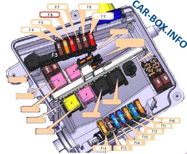
Fuse box diagram.
| No. | Rating (A) | Description |
| F1 | - | Not used |
| F2 | - | Not used |
| F3 | 50 | X62 option bus |
| F4 | 40 | ABS ECU |
| F5 | 50 | Auxiliary heater relay 1 |
| F6 | 50 | Special body conversion (X62 option bus) |
| F7 | 70 | Auxiliary heater relay 2 |
| F8 | 70 | Rear lighting, passenger compartment fuse/relay box, diesel pre-heater heating element |
| F9 | 70 | Passenger compartment fuse and relay box |
| F10 | 50 40 |
Engine cooling fan relay 3 (rating depends on vehicle equipment) |
| F11 | 40 50 60 |
Engine cooling fan speed relays 1 & 2 (rating depends on vehicle equipment) |
| F12 | 40 | Starter motor / Engine start |
| F13 | 60 | Heating interface unit |
| F14 | 60 | Heating interface unit |
| F15 | 70 | Diesel glow plug control unit |
| F16 | 40 | Automated transmission hydraulic pump unit relay |
| 50 | Auxiliary fuse box 2 | |
| AUXILIARY / BODYBUILDER POWER BOARD (260BA) | ||
| F1 | 5 | Gruau lighting control unit (front and rear lighting) |
| F2 | 5 | Gruau interior lighting control unit (X81 options) |
| F3 | 15 | Relay 1155 power supply (70 A auxiliary load relay) |
| F4 | 25 | Power relay 1155 (70 A BCM battery relay) |
| F5 | 10 | Multimedia display power supply (Gruau equipment) |
| F6 | 5 | Electric side step control unit |
| F7 | - | Not used |
| F8 | - | Not used |
Passenger Compartment
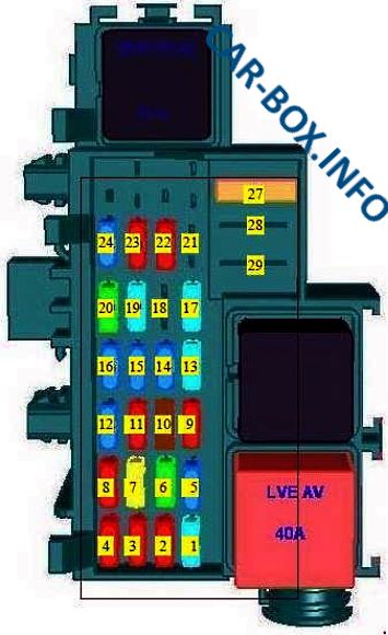
Passenger Compartment Fuse Box
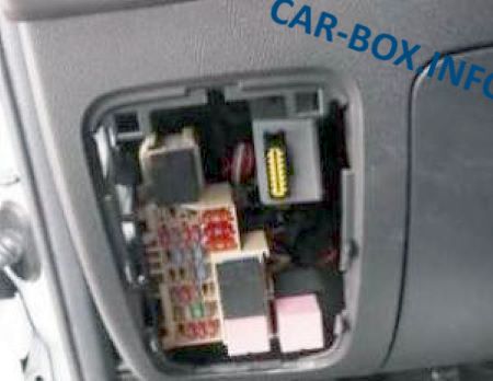
Located on the driver’s side of the dashboard, behind a plastic trim panel.
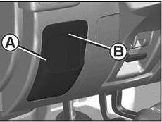
To gain access, use cutout (B) to detach cover (A).
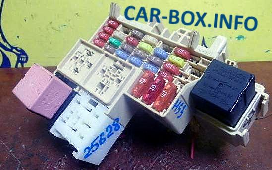
Overview.
| Diagram | ||
|---|---|---|
|
||
| No. | Rating (A) | Description |
| 1 | 10 | Infotainment system, heated seats, engine run relay 1 |
| 2 | 15 | Cigarette lighter socket |
| 3 | 10 | Auxiliary power outlet 1 |
| 4 | 10 | Auxiliary power outlet 2 |
| 5 | 5 | Instrument cluster |
| 6 | 30 | Central locking system (Body Control Module / BCM) |
| 7 | 25 | Direction indicators, rear fog lights, Body Control Module (BCM) |
| 8 | 5 | OBD2 / Diagnostic connector |
| 9 | - | Not used |
| 10 | 5 | ABS, Electronic Stability Program (ESP) |
| 11 | 10 | Interior lighting, brake lights |
| 12 | 5 | Body Control Module (BCM) |
| 13 | 15 | Brake light switch |
| 14 | 5 | Body Control Module (BCM), power windows, climate control |
| 15 | 20 | Heated rear window (left-hand) |
| 16 | 20 | Heated rear window (right-hand) |
| 17 | 15 | Windshield washer pump, steering column stalk controls |
| 18 | 5 | Engine immobilizer system |
| 19 | 15 | Heated seats (auxiliary options module) |
| 20 | - | Not used |
| 21 | 10 | Cornering lights / Turn signals |
| 22 | 10 | Infotainment system, heated seats, display screen, audio jacks, alarm system |
| 23 | 5 | Hands-free telephone module |
| 24 | 10 | Tachograph |
| 25 | - | - (Diode location) |
| 26 | - | - (Diode location) |
| 27 | 40 | Climate control blower motor |
| 28 | 10 | Accessories power supply / Auxiliary relay |
| 29 | 40 | Power windows, Body Control Module (BCM) |
Fuses 2 and 3 supply power to the cigarette lighter and front auxiliary power outlet.
Auxiliary Relay & Fuse Blocks
These blocks are located under the dashboard on the right-hand side (on both LHD and RHD vehicles) and are attached to the dashboard cross-member mounting bracket.
Block No. 1
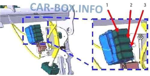
- 12 V power supply for load current sharing (20 A)
- Engine running signal (20 A)
- Heated seats (20 A)
Block No. 2
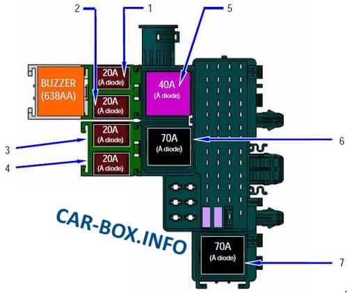
- Power sliding door (20 A)
- Tailgate / Rear doors (20 A)
- Minibus passenger heated seats (20 A)
- Minibus ESP module (20 A)
- Air conditioning control feed (40 A)
- BCM battery main power feed (70 A)
- Roof harness / Bodybuilder auxiliary power feed (70 A)
