Renault Modus was produced in 2004, 2005, 2006, 2007, 2008, 2009, 2010, 2011 and 2012. After restyling, it is also known as the Grand Modus.
We will show the location of fuse and relay blocks in Renault modus, their photos, diagrams and the purpose of the elements. The fuse responsible for the “Cigarette lighter” is highlighted in bold.
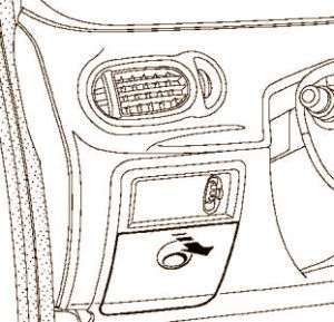
In the passenger compartment
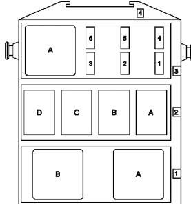
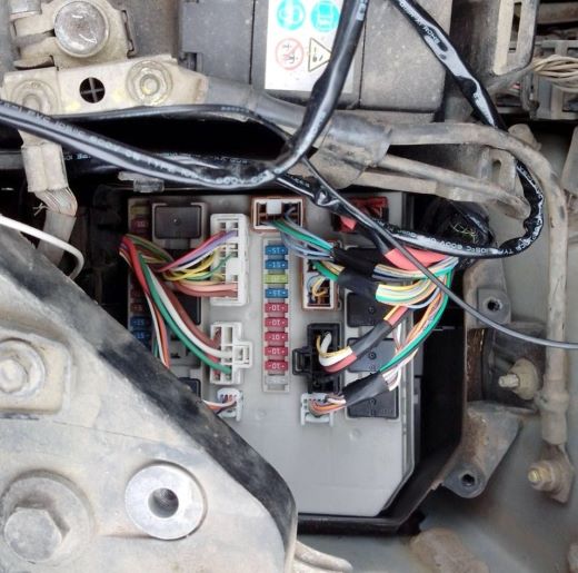
Main block located in the passenger compartment on the lower left side of the dashboard.
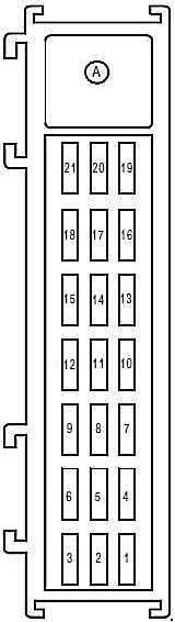
Fuse box №1
On the back of the protective cover there will be an up-to-date diagram showing the location of the fuses.
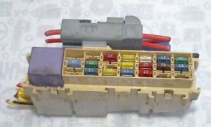
Photo - example.
| Assignment of the fuses in the passenger compartment | |
|---|---|
|
|
| № | Amps / Description |
| F1 | 30A UCH |
| F2 | 15A Instrument panel, air conditioning control unit, fuse and relay box |
| F3 | Not used |
| F4 | Main electromagnetic signal, diagnostic connector, display |
| F5 | 7.5A UCH |
| F6 | 25A Driver power window motor, child seat safety control |
| F7 | 25A Electric driver window control |
| F8 | 10A ABS, ESP |
| F9 | 10A Cigarette lighter Renault Modus |
| F10 | 20A Passenger Fan |
| F11 | 20A Passenger Fan |
| F12 | 15A Air conditioning control unit, radio, steering wheel control, telephone, heated seats, alarm. |
| F13 | 10A Passenger compartment fuse and relay box |
| F14 | Empty |
| F15 | 20A Rear wiper motor |
| F16 | 30A Electric mirrors |
| F17 | 30A UCH |
| F18 | 15A UCH, engine immobilizer |
| F19 | 5A Rain and light sensor, interior motion sensor |
| F20 | 10A Instrument panel, radio, alarm, air suspension pressure control system |
Fuse box №2
Attached to the cross member of the dashboard, under the passenger airbag.
| Diagram | |
|---|---|
|
|
| № | Amps / Description |
| F1 | 20A Relay for emergency opening of the driver's and passenger's doors |
| F2 | 20A Heated driver and passenger seats |
| F3 | 15A Roof hatch |
| F4 | 25A Power window relay |
| F5 | Not used |
| F6 | Not used |
Fuse boxes under the hood
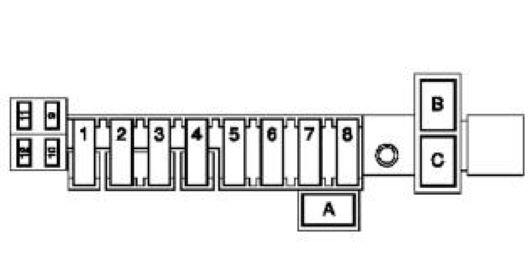
Block #1
This unit is located in the engine compartment behind the left headlight. To access the distribution box, remove the drip tray under the air intake grille.
| Assignment of the fuses in the engine compartment | |
|---|---|

|
|
| № | A - Description |
| 100 | 25A ABS computer or electronic stabilization program |
| 101 | Not used |
| 102 | 10A Right high beam headlamps |
| 103 | 10A Left high beam headlamp |
| 104 | 10 Right light, right seat heating control, electronic stability on / off button, rear right electric window control, climate control panel, air conditioning control unit, central door lock, electric door mirror and window control. |
| 105 | 10A Left side light, left seat heating, first row cigarette lighter, display with gear lever, power window control |
| 106 | 15A Direction indicators, auxiliary heater relay, power shift lever, hands-free kit, telephone, tire pressure indicator |
| 107 | 20A Wiper motor |
| 108 | 15A Right drive headlights / right headlight range control |
| 109 | 15A Left headlight motor / left headlight |
| 300 | 10A Air conditioner |
| 301 | Not used |
| 302 | 25A Starter |
| 303 | 20A Computer |
| 304 | Not used |
| 305 | 15A Heated rear window |
| 306 | 15A Headlight washer power relay (relays A and B on the board) |
| 307 | 5A Computer |
| 308 | Not used |
| 309 | 10A Reversing lights |
| 310 | 20A Ignition coils |
| 311 | 20A Power supply |
| 312 | 10A Airbag |
| 313 | 10A Computer |
| 314 | 20A Front left and right fog lamps |
| Relay | |
| 1 | Heated rear window |
| 2 | Injection blocking |
| 3 | Low beam headlights |
| 4 | Headlights |
| 5 | Starter |
| 6 | Not used |
| 7 | High speed motor cooling fan |
| 8 | Low speed motor cooling fan |
| 9 | Ignition feed |
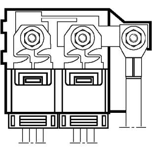
Block #2
This unit is located on the front wall of the battery shelf.
| Diagram | |
|---|---|
|
|
| № | A - Description |
| F1 | 30A Central injection unit power relay on K9K or 764 engine / 30 Preheating |
| F3 | 30A Air conditioner fan / 30A A / C fan, pump relay |
| F5 | 50A Fuses F1, F2, F3, F4 |
| F6 | 80A Additional passenger heater |
| F7 | 60A Additional passenger heater |
| F8 | 50A Computer ABS |
| F9 | Not used |
| F10 | Not used |
| F11 | Not used |
| F12 | 10A Left headlight power sensor |
| Relay | |
| A | 20A Headlight washer pump |
| B | 20A Headlight washer pump relay |
| C | 20A headlights |
Block #3
This power fuse box is located on the positive terminal of the battery.
