Skoda Superb second generation B6 premiered at the 2008 Geneva Motor Show. The following year, the company presented the Superb Combi station wagon. The business class car replaced the first generation model and was produced until 2015. In this article, we will take a detailed look at the fuse box diagrams for the Skoda Superb (2nd generation; codename 3T / 6B) 2008, 2009, 2010, 2011, 2012, 2013, 2014, 2015 years of manufacture.
Here you will find the locations and photos of distribution boxes. The fuses responsible for the “Cigarette lighter” and “Fuel Pump” are highlighted in bold.
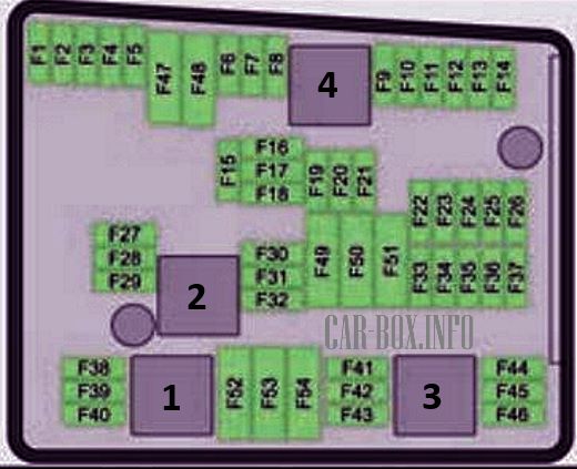
In the engine compartment
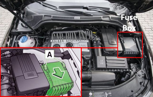
It is located near the battery. The protective cover must be removed for access.
General view.
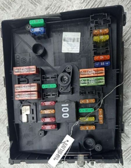
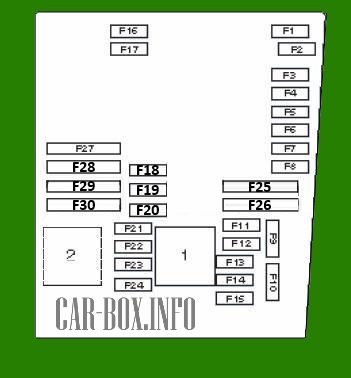
Type 1
Diagram.
|
||
| No. | Description of fuses | A |
| F1 | Empty | - |
| F2 | DSG gearbox | 5 |
| F3 | Multifunctional control unit | 5 |
| F4 | ABS / ESP system | 20 / 30 |
| F5 | DSG gearbox | 15 |
| F6 | Spare | 5 |
| F7 | Spare | 40 |
| F8 | Spare | 15 |
| F9 | Telephone | 5 |
| F10 | Engine management | 5 / 10 |
| F11 | Additional heater | 20 |
| F12 | Diagnostic unit | 5 |
| F13 | Engine management | 15 / 30 |
| F14 | 20 | |
| F15 | Spare | 5 / 10 |
| F16 | Multifunctional control unit | 30 |
| F17 | Horn (beep) | 15 |
| F18 | Audio amplifier | 30 |
| F19 | Windshield wiper | 30 |
| F20 | Spare | 10 / 15 / 20 |
| F21 | Engine management | 10 / 15 |
| F22 | Spare | 5 |
| F23 | Spare | 5 / 10 / 15 |
| F24 | Spare | 10 |
| F25 | ABS / ESP system | 30 / 40 |
| F26 | Multifunctional control unit | 30 |
| F27 | Glow plugs | 50 |
| F28 | Heated windshield | 50 |
| F29 | Spare | 50 |
| 1 | Empty | - |
| 2 | Empty | - |
Type 2
Diagram.
|
||
| No. | Decoding | A |
| F1 | Multifunctional control unit | 30 |
| F2 | ABS / ESP system | 20 |
| F3 | Empty | - |
| F4 | Empty | - |
| F5 | Horn | 15 |
| F6 | Empty | - |
| F7 | Empty | - |
| F8 | Empty | - |
| F9 | Engine management | 10 |
| F10 | Empty | - |
| F11 | Engine management | 10 |
| F12 | 10 | |
| F13 | DSG gearbox | 15 |
| F14 | Empty | - |
| F15 | Coolant pump | 10 |
| F16 | Empty | - |
| F17 | Spare | 5 |
| F18 | Audio amplifier | 30 |
| F19 | Audio / navigation system | 15 |
| F20 | Telephone | 5 |
| F21 | Empty | - |
| F22 | Empty | - |
| F23 | Engine management | 10 |
| F24 | Diagnostic unit | 5 |
| F25 | Empty | - |
| F26 | Empty | - |
| F27 | Engine management | 15 |
| F28 | 15/20 | |
| F29 | 5 | |
| F30 | Additional heater | 20 |
| F31 | Windshield wiper | 30 |
| F32 | Empty | - |
| F33 | Empty | - |
| F34 | Empty | - |
| F35 | Empty | - |
| F36 | Empty | - |
| F37 | Empty | - |
| F38 | Cooling fan motor control unit | 10 |
| F39 | Spare | 5/10 |
| F40 | Engine management | 7.5 / 10 |
| F41 | 10 | |
| F42 | 5/10 | |
| F43 | 30 | |
| F44 | Empty | - |
| F45 | Empty | - |
| F46 | Empty | - |
| F47 | Multifunctional control unit | 30 |
| F48 | ABS / ESP system | 40 |
| F49 | Main ignition circuits | - |
| F50 | Empty | - |
| F51 | Empty | - |
| F52 | Auxiliary circuits | 40 |
| F53 | Spare | 50 |
| F54 | Empty | - |
| 1 | Empty | - |
| 2 | Coolant pump relay | - |
| 3 | Empty | - |
| 4 | Empty | - |
In the passenger compartment
There are two distribution boxes here that are responsible for protecting the electrical circuits.
Fuse box
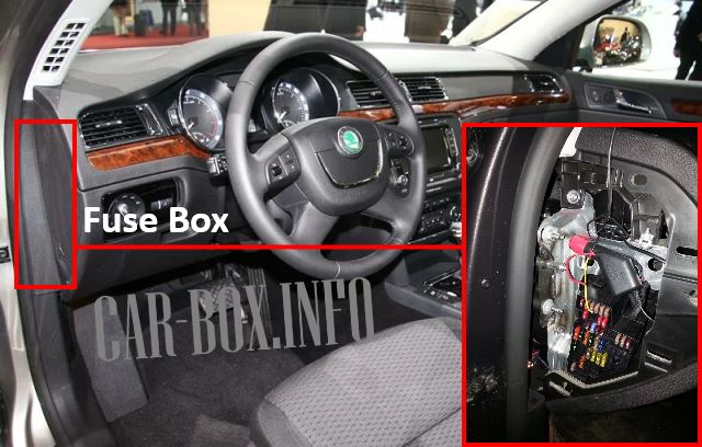
It is located at the end of the dashboard. It can be accessed by removing a part of the trim.
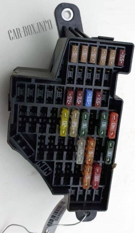
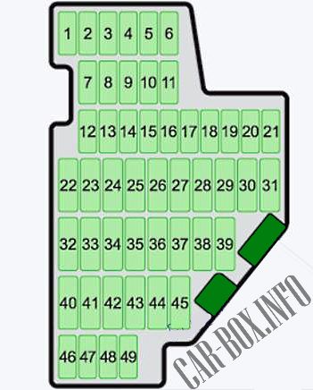
General view of the Skoda Superb interior fuse box.
| Diagram | ||
|---|---|---|
|
||
| No. | Description | A |
| F1 | Diagnostic connector, engine ECU, fuel pump relay, gasoline pump ECU | 7.5 |
| F2 | ABS ECU, ESC, tire pressure monitoring indicator switch, brake sensor | 5 |
| F3 | SRS System, Airbag Switch | 5 |
| F4 | Service interval extension indicator, tail light, tinted mirror, pressure sensor, cell phone connection kit | 5 |
| F5 | Headlight corrector and headlight tilt, parking assist system | 5 |
| F6 | Instrument cluster, power steering, Haldex, selector lever lock, power supply for data bus, automatic transmission | 5 |
| F7 | Engine management, Valve heater, Air flow meter | 10 |
| F8 | Trailer control unit | |
| F9 | Heater fan motor, Auxiliary heater and ventilation relay | 5 |
| F10 | Headlight (left) | 10 |
| F11 | Headlight (right) | 10 |
| F12 | Spare | 10 |
| F13 | Diagnostic connector, light switch, rain sensor, clock | 7.5 |
| F14 | Central locking and luggage compartment lid | 15 |
| F15 | interior lighting | 7.5 |
| F16 | Climate control unit | 7.5 |
| F17 | Spare | 10 |
| F18 | Telephone | 5 |
| F19 | Instrument cluster, wiper arm and turn signal switch | 5 |
| F20 | KESSY | 5 |
| F21 | Steering column lock | 7.5 |
| F22 | Heater fan motor | 40 |
| F23 | Front power windows, front door central locking | 30 |
| F24 | Automatic transmission | 5 |
| F25 | Rear window heater, autonomous heater and ventilation relay | 25 / 30 |
| F26 | Accessory power socket, Luggage compartment socket | 25 |
| F28 | Trunk lid/rear door opening actuator | 30 |
| F29 | Automatic transmission, Haldex clutch | 5 / 10 / 20 |
| F30 | Front seat ventilation system | 5 |
| F31 | DVD-player | 5 |
| F32 | Rear power windows, rear door central locking | 30 |
| F33 | Electric sliding sunroof actuator | 25 |
| F34 | Anti-theft system, alarm system, siren | 5 |
| F35 | Accessory Power Connectors, Superb Cigarette Lighter Fuse (Front, Rear) | 25 |
| F36 | Headlight washers | 20 |
| F37 | Heated front seats | 20 |
| F38 | Heated rear seats | 20 |
| F39 | Rear window wiper | 10 |
| F40 | Heater fan motor, auxiliary heater and ventilation relay | 40 |
| F41 | Rear window wiper | 10 |
| F42 | Light switch | 5 |
| F43 | Trailer control unit | 15 |
| F44 | 20 | |
| F45 | 15 | |
| F46 | Seat heating switch | 5 |
| F47 | Telephone | |
| F48 | Audio / navigation system | 5 |
| F49 | Spare | |
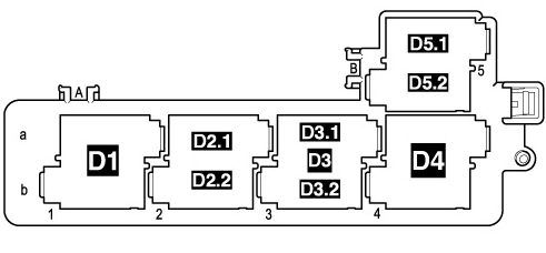
Additional relay box

It's located behind the glove compartment. It consists of 2 parts. The board above the central control unit and the board under the CCU.
| Relay circuits (Type 1) | |
|---|---|
| Top board | |
|
|
| No. | Description |
| D1 | Independent heater relay (on models with independent auxiliary heater) or Relay for low heat output (for models with auxiliary resistance heater (RTS)) |
| D2.1 | Horn |
| D2.2 | Fuel pump relay (for BUD, CGGA, BSE, BSF, CMXA, CHGA engines) / Additional fuel pump relay -J832- (for CLCA, CLCB, CFHF, CFHC, CEGA engines) |
| D3 | Relay for high heat output (on models with optional resistance heater (RTS)) |
| D3.1 | Fresh air inlet fan (on models with independent auxiliary heater) |
| D3.2 | Auxiliary heater fuel pump relay -J749- (on models with independent auxiliary heater) |
| D4 | Starter |
| D5.1 | Headlamp washers |
| D5.2 | relay for heating element (at engine lettering CAYC) |
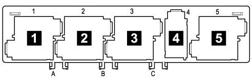
| Bottom board | |
|
|
| No. | Description |
| 1 | supply voltage relay (15) |
| 2 | rear window heater relay |
| 3 | supply voltage relay (50) starter relay 1 |
| 4 |
|
| 5 | switching relay for contact X |
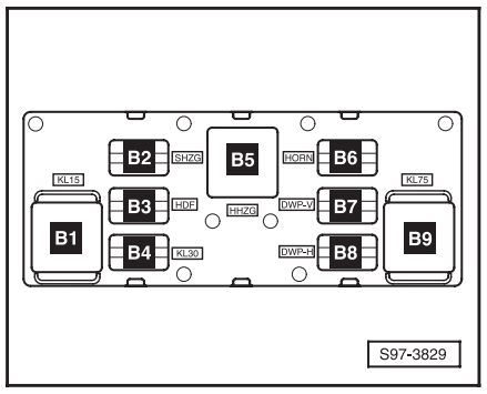
| Relay circuit (Type 2) | |
|---|---|
|
|
| B4 | supply voltage (30) |
| B5 | rear window heater |
| B6 | horn |
| B7 | glass washer pump 1 |
| B8 | glass washer pump 2 |
| B9 | switching relay for X contact |
