The Superb sedan is the flagship of the Skoda model range. The first generation was released in 2001. The model is based on the Chinese-made Volkswagen Passat, which differs from the European version by 10 cm longer wheelbase. In this article, we will take a detailed look at the fuse box diagrams for the Skoda Superb (1st generation; codename 3U4) 2001, 2002, 2003, 2004, 2005 and restyling 2006, 2007, 2008 years of manufacture.
Here you will find the locations and photos of distribution boxes. The fuses responsible for the “Cigarette lighter” and “Fuel Pump” are highlighted in bold.
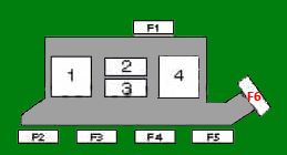
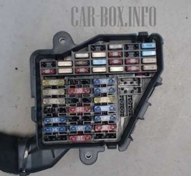
In the engine compartment
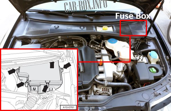
It is located in the upper part of the underhood. It can be accessed by removing a part of the cladding.
| Diagram | |
|---|---|
|
|
| No. | Description |
| F1 | Motor control 15 A |
| F2 | Empty |
| F3 | Exhaust air pump (gasoline), 2 glow plug fuse (40A / 60A depending on equipment) |
| F4 | Empty |
| F5 | Glow plugs (60A / 80A) |
| F6 | Coolant pump motor (fuel system) (10A) - depending on equipment |
| 1 | Empty |
| 2 | Exhaust air pump relay |
| 3 | Cooling pump motor relay (fuel system) - depending on equipment |
| 4 | Engine control relay |
In the passenger compartment
There are two distribution boxes here that are responsible for protecting the electrical circuits.
Fuse box
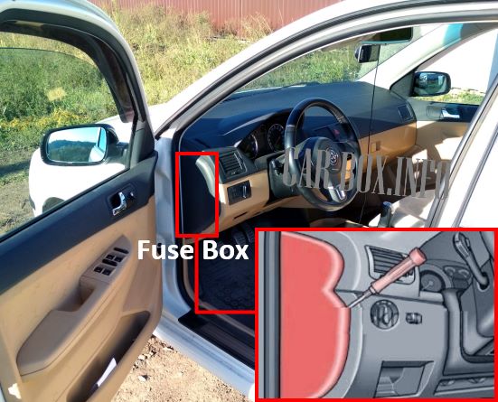
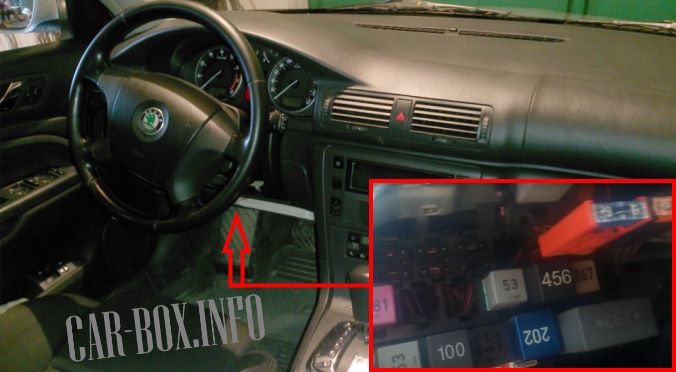
Located in the driver's side end of the dashboard.
General view of the Skoda Superb interior fuse box.
| Diagram | ||
|---|---|---|

|
||
| No. | Decoding | A |
| 1 | Windshield washer nozzle heaters | 5 |
| 2 | Direction indicators | 10 |
| 3 | Taximeter (03/03 ^) - if available | 5 |
| 4 | License plate illumination lamps | 5 |
| 5 | Air conditioning, lights, diagnostic connector (DLC), seat heater, instrument cluster, steering wheel mounted switches, telephone | 10 |
| 6 | Heated door mirrors, central locking system | 5 |
| 7 | ABS brake light switch (brake pedal position sensor), clutch pedal limit switch (position sensor) | 10 |
| 8 | Headlights corrector | 5 |
| 9 | Parking system | 5 |
| 10 | Steering wheel switches, telephone | 5 |
| 11 | Power seat (with memory) | 5 |
| 12 | Diagnostic connector (DLC) | 10 |
| 13 | Stop lights | 10 |
| 14 | Additional equipment, central locking, interior lamps | 10 |
| 15 | Air conditioning system, automatic transmission, instrument cluster | 10 |
| 16 | Electronic Stability Program (ESP) | 5 |
| 17 | Cab alarm system, audio unit for cab (03/03^) - if available | 10 |
| 18 | Right headlight - high beam | 10 |
| 19 | Left headlight - high beam | 10 |
| 20 | Right headlight - dipped beam, headlight corrector | 15 |
| 21 | Left headlight - dipped beam, headlight corrector | 15 |
| 22 | Front and rear right parking light bulbs | 5 |
| 23 | Front and rear left parking light bulbs | 5 |
| 24 | Windshield wiper / washer | 25 |
| 25 | Air conditioner / heater fan motor, air conditioner | 30 |
| 26 | Rear window heater | 20 |
| 27 | Empty | |
| 28 | Skoda Superb fuel pump fuse | 20 |
| 29 | Engine management | 20 |
| 30 | Sunroof | 20 |
| 31 | Automatic transmission, taximeter, audio unit for cabs, reverse lights | 15 |
| 32 | Engine management | 20 |
| 33 | Skoda Superb cigarette lighter fuse | 15 |
| 34 | Engine management | 15 |
| 35 | Trailer electrical connector - terminal 30 | 30 |
| 36 | Fog lights | 15 |
| 37 | Audio system, navigation system | 20 |
| 38 | Additional equipment, door function control units | 15 |
| 39 | Alarm (hazard) | 15 |
| 40 | Sound signal (horn) | 25 |
| 41 | Audio unit for cab (03/03^) - if available | 10 |
| 42 | Anti-lock braking system (with ESP) | 25 |
| 43 | Engine management | 15 |
| 44 | Seat heater | 30 |
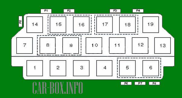
Relay box
Additional relay blocks are located under the dashboard next to the main block.
| Diagrams | |
|---|---|
| Relay Box No. 1 | |

|
|
|
|
| No. | Decoding |
| F1 | - |
| F2 | Audio system amplifier (^04/02), auxiliary equipment power connector - duffel box (03/03^) |
| F3 | Brake booster vacuum pump (if installed) - 15A |
| F4 | Optional equipment connection socket (cigarette lighter, rear) - 20A |
| F5 | Backlight - 30A |
| F6 | Accessory power connector - luggage compartment - 20A |
| F7 | Anti-theft system 1 (cab) - 03/03^ - 20A |
| F8 | Anti-theft system 2 (cab) -03/03^ - 25A |
| 1 | Horn relay (dual tone) |
| 2 | Ignition auxiliary relay |
| 3 | - |
| 4 | Fuel pump relay Superb (petrol engines), or glow plug relay (diesel) |
| 5 | Windshield wiper/washer intermittent operation relay |
| 6 | |
| 7 | Fog lamp relay |
| 8 | Multifunction steering wheel control module |
| 9 | |
| 10 | fuel pump relay, brake booster vacuum pump relay, if available |
| 11 | Backlight relay |
| 12 | A/C compressor solenoid clutch relay -ATC (05/02^), A/C compressor control unit - MTC (05/02^) |
| 13 | No-start switch relay (with automatic transmission), cab alarm system control unit 2 (03/03^) |
| 14 | Cooling fan motor relay (^ 02/03), rear defogger relay (03/03 ^) |
| 15 | Lamp test system unit |
| 16 | |
| 17 | Rear window heater relay (^02/03), heater fan motor cut-off relay (sunroof) - 08/03^, cab alarm system control unit 1 (03/03^) |
| 18 | Taxi alarm system control unit 1 (03/03 ^) |
| 19 | A/C compressor solenoid clutch relay - ATS (^04/02), A/C compressor control unit - MTC (^04/02), cooling system fan motor relay (03/03^) |
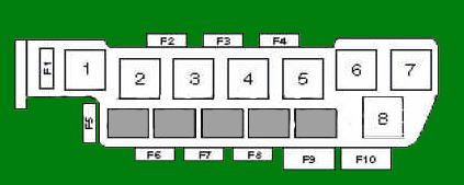
| Board No. 2 | |
|
|
| No. | Description |
| F1 | Anti-theft alarm sound - 10A |
| F2 | Fuse for the power seat drive circuit, passenger side - 30A |
| F3 | Fuse for the power seat drive circuit, driver's side - 30A |
| F4 | Turn indicators (central locking remote control) - 15A |
| F5 | Audio amplifier (05/02 ^) - 30A |
| F6 | Anti-theft system (^ 11/02) - 15A |
| F7 | Thermal fuse of the electric window lifters - 30A |
| F8 | Cooling fan - 5A |
| F9 | Cooling fan - 40A |
| F10 | Anti-lock braking system (ABS) - 50A |
| 1 | Cooling fan motor cut-out relay (after engine stop) |
| 2 | Cooling fan motor relay - 2nd speed |
| 3 | Cooling Fan Motor Relay - 1st Speed |
| 4 | Empty |
| 5 | Empty |
| 6 | Empty |
| 7 | Empty |
| 8 | Empty |
