The third-generation Superb is built on the MQB platform (Volkswagen development) and inherits the design of the not-so-famous green VisionC concept car, which Skoda demonstrated at the Geneva and Moscow motor shows in 2014. In this article, we will take a detailed look at the fuse box diagrams for the Skoda Superb 3rd generation (3V/B8) 2015, 2016, 2017, 2018, 2019, 2020, 2021 years of manufacture.
Here you will find the locations and photos of distribution boxes. The fuses responsible for the “Cigarette lighter” and “Fuel Pump” are highlighted in bold.
In the engine compartment
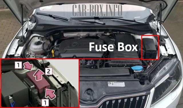
It is located on the left side of the underhood behind the protective cover. To access it, press the catches (1) and pull upwards (2).
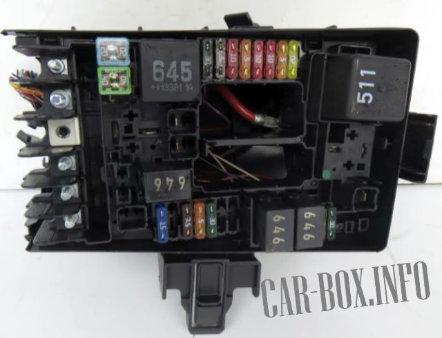
General view.
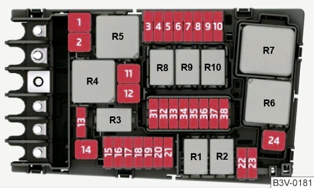
| Diagram | ||
|---|---|---|
|
||
| No. | Description of fuses | A |
| 1 | ABS control module ABS control module |
25 |
| 2 | 40/60 | |
| ABS hydraulic pump | ||
| 3 | Engine / engine control unit | 15 |
| 30 | ||
| 4 | Radiator fan | 5 / 7.5 |
| Low and high heat output relays | ||
| Oil pressure control valve | ||
| Turbocharger air recirculation valve | ||
| Inlet manifold damper valve | ||
| Piston cooling nozzle control valve | ||
| Oil level and temperature sensor | ||
| Turbine switching valve | ||
| Motor component power relay | ||
| 5 | Fuel pressure control valve | 10 |
| Fuel dosing valve | ||
| Motor component power relay | ||
| Turbine switching valve | ||
| 6 | Stop lamp switch | 5 / 7.5 |
| 7 | Charge air cooling pump | 7.5 / 10 |
| Transmission coolant valve | ||
| Coolant shut-off valve | ||
| Additional heating system pump | ||
| Cylinder head coolant valve | ||
| Oil pressure control valve | ||
| Fuel tank control module leak detection | ||
| 8 | Lambda probes before and after the catalytic converter | 15 |
| NOx Sensor Control Modules | ||
| 9 | Exhaust flap control modules | 5/10 |
| Automatic glow plug control module | ||
| Crankcase breather heating element | ||
| Air mass meter | ||
| Heating system auxiliary pump | ||
| Solenoid valve 1 of the activated carbon filter | ||
| Timing adjustment valves | ||
| 10 | Skoda Superb 3 fuel pump fuse | 15/20 |
| 11 | Auxiliary air heater element | 40/50 |
| 12 | 40 | |
| 13 | Transmission oil auxiliary hydraulic pump 1 | 30 |
| 14 | Heated windshield relay | 40 |
| 15 | Horn relay | 15 |
| 16 | Motor component power relay | 20 |
| 17 | Engine / engine control unit | 7.5 |
| ABS system | ||
| Heated windshield relay | ||
| 18 | Battery control module | 5 / 7.5 |
| Data bus diagnostic interface | ||
| 19 | Wiper Motor Control Module | 30 |
| 20 | Horn (beep) | 10 |
| 21 | Heated windscreen relay 2 | 30 |
| 22 | Engine / engine control unit | 5 / 7.5 |
| 23 | Starter | 30 |
| 24 | Auxiliary air heater element | 40 |
| 31 | Empty | - |
| 32 | Empty | - |
| 33 | Heated windscreen relay 2 | 30 |
| 34 | 30 | |
| 35 | Wiper Motor Control Module | 30 |
| 36 | Empty | - |
| 37 | Auxiliary heater control module | 30 |
| 38 | Empty | - |
| Relay modules | ||
| R1 | Starter | |
| R2 | ||
| R3 | Horn relay | |
| R4 | High heat output relay | |
| R5 |
|
|
| R6 | Glow control ECU (petrol) | |
| R7 | Low heat output relay (diesel) | |
| R8 | Engine component power relay (2.0 liter gasoline engine) | |
| R9 | Heated windshield | |
| R10 | ||
In the passenger compartment
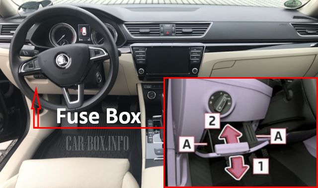
Skoda Superb LHD: is located on the driver's side behind the glove compartment. To access it, press the catches "A" and pull out the box itself.

Right-hand drive models: is located on the passenger side behind the glove box. The glove box must be removed for access.
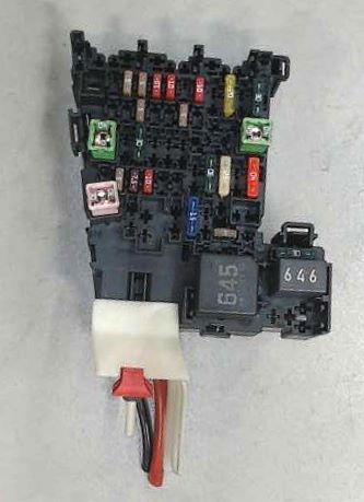
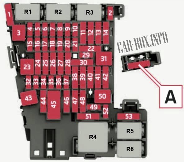
General view of the Skoda Superb interior fuse box.
| Diagram | ||
|---|---|---|
|
||
| No. | Description | A |
| 1 | Reconditioner heater control module | 30 |
| 2 | Steering column control module | 10 |
| 3 | Empty | - |
| 4 | Sound signal (horn) | 7.5 / 10 |
| 5 | Data bus diagnostic interface | 5 / 7.5 |
| 6 | Selector lever | 5 / 7.5 |
| 7 | Heater and air conditioning controls | 10 |
| Rear air conditioning control and display module | ||
| Remote control of the autonomous heater | ||
| Rear window heating | ||
| Clock | ||
| Tire Pressure Monitoring System Control Module | ||
| 8 | Rotary light switch | 7.5 / 10 |
| Button for the electro-mechanical parking brake | ||
| Rain and light sensor | ||
| OBD diagnostic connector | ||
| Burglar alarm sensor | ||
| Background lighting LED left and right | ||
| Front interior lighting | ||
| Burglar alarm sensor | ||
| Control module for cornering light and headlamp angle corrector, door lighting | ||
| door lamps | ||
| 9 | Steering column control module | 5 / 7.5 |
| 10 | Control module for front information display and control unit | 7.5 / 10 |
| Head-up display control module | ||
| 11 | On-board network control module | 40 |
| 12 | Electronic information system control module 1 | 20 |
| Navigation control module | ||
| 13 | Front left seat belt | 25 |
| 14 | Supply fan control module | 40 |
| 15 | Electronic steering column lock control module | 10 |
| 16 | Two-way signal booster for cell phone / data services | 7.5 |
| USB charging port 1 | ||
| Storage compartment with cell phone interface | ||
| USB hub | ||
| 17 | Emergency call module and communication unit | 7.5 |
| 18 | Top view camera control module | 7.5 |
| Trunk lid handle | ||
| Top-mounted rearview camera | ||
| 19 | Interface for login and startup system | 7.5 |
| 20 | Dosing system relay | 7.5 / 10 |
| Vacuum pump relay | ||
| 21 | Four-wheel drive control module | 15 |
| 22 | Trailer recognition control module | 15 |
| 23 | Sliding sunroof control module | 20/30 |
| 24 | Onboard supply control module | 40 |
| 25 | Driver's door control module | 30 |
| Driver's rear door module | ||
| 26 | Onboard supply control module | 30 |
| 27 | 30 | |
| 28 | Trailer recognition control module | 25 |
| 29 | Remote start relay | 5 |
| 30 | 10 | |
| 31 | Trunk lid control unit | 30 |
| 32 | Driver auxiliary systems front camera | 10 |
| Adaptive cruise control control unit | ||
| Parking assistant control unit | ||
| Lane change assist control unit | ||
| 33 | Airbag control unit | 5 / 7.5 |
| 34 | Internal mirror | 7.5 |
| Socket relay | ||
| Back-up lamp switch | ||
| Refrigerant circuit pressure sensor | ||
| Air quality sensor | ||
| Central switch box in the front panel | ||
| Switch block 1 in the center console | ||
| Sound Control Unit | ||
| Parking brake button | ||
| 35 | OBD diagnostic connector | 7.5 / 10 |
| 36 | Headlight, front right | 5 / 7.5 |
| 37 | Front left headlight | 5 / 7.5 |
| 38 | Trailer detection control unit | 25 |
| 39 | Front and rear passenger door control unit | 30 |
| 40 | Skoda Superb 3 cigarette lighter fuse, 12 V sockets | 20 |
| 41 | Front right seat belt | 25 |
| 42 | Onboard supply control unit | 40 |
| 43 | Digital audio system control unit | 40 |
| 44 | Trailer detection control unit | 15 |
| 45 | Driver's seat adjustment control unit | 15 |
| Front left seat cushion fan 1 | ||
| Front left seat backrest fan 1 | ||
| 46 | DC / AC converter with socket, 12 V - 230 V | 30 |
| 47 | Empty | - |
| 48 | Empty | - |
| 49 | Clutch position sensor | 5 / 7.5 |
| Starter relay | ||
| 50 | Trunk lid control unit | 40 |
| 51 | Rear air conditioning control and display unit | 25 |
| 52 | Electronically controlled damping control unit | 15 |
| 53 | Rear window heater relay | 30 |
| The individual components are located inside the fuse box holder: | ||
| A | Front right seat position adjustment control unit | 15 |
| Front right seat cushion fan | ||
| B | Remote start relay | 5 |
| C | USB connector for charging | 7.5 |
| R1 | Remote start relay | |
| No. | Purpose of relay modules | |
| R1 | reducing agent dosing system | |
| R2 | Empty | |
| R3 | Empty | |
| R4 | power supply terminal 15 | |
| R5 | rear window heating | |
| R6 | 12V power outlets | |
