
Table of Contents
Most power supply circuits in the sedan are protected by fuses. High-current components such as headlights, fan motors, and the fuel pump are connected via relays. Fuses and protective devices are housed in power distribution boxes located in both the passenger compartment and the engine compartment.
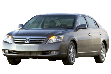
Applies to Toyota Avalon 3rd generation (chassis code XX30; K platform) 2005, 2006, 2007, 2008, 2009, 2010, 2011, and 2012 model years.
Engine Compartment
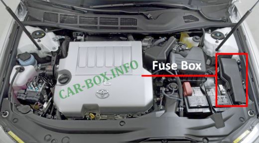
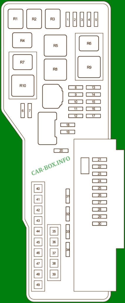
The fuse box is located on the left side of the engine compartment, near the battery.
| Diagram | ||
|---|---|---|
|
||
| No. | Circuit Protected | A |
| 1 | EFI NO. 2: Multiport fuel injection system / sequential multiport fuel injection system | 10 |
| 2 | Stop lamps, high-mounted stop lamp, Vehicle Stability Control (VSC) system, Anti-lock Braking System (ABS) | 7.5 |
| 3 | 2005–2010: Vehicle Stability Control (VSC) system | 7.5 |
| 4 | Right headlight (low beam) | 15 |
| 5 | Left headlight (low beam) | 15 |
| 6 | 2008–2012: Electronically controlled transmission system, multiport fuel injection system / sequential multiport fuel injection system | 7.5 |
| 7 | Multiport fuel injection system / sequential multiport fuel injection system | 15 |
| 8 | Empty | - |
| 9 | Multiplex communication system | 15 |
| 10 | 2005–2010: Steering lock system | 25 |
| 2011–2012: Steering lock system | 15 | |
| 11 | 2005–2007: Engine immobilizer system, Smart Key system | 7.5 |
| 2008–2012: Smart Key system, electronically controlled transmission system | 7.5 | |
| 12 | Audio system | 30 |
| 13 | Empty | - |
| 14 | Short Pin NO. 1 | - |
| 15 | Audio system, center display, navigation system | 15 |
| 16 | Center display, multiplex communication system | 10 |
| 17 | Gauges and meters, clock, front interior lights, door courtesy lights, garage door opener, rear interior lights, trunk light | 7.5 |
| 18 | Turn signal lamps | 15 |
| 19 | Multiport fuel injection system / sequential multiport fuel injection system | 25 |
| 20 | Empty | - |
| 21 | Horn | 7.5 |
| 22 | Windshield washer | 20 |
| 23 | Air-fuel ratio (A/F) sensor | 25 |
| 24 | Right headlight (high beam) | 15 |
| 25 | Left headlight (high beam) | 15 |
| 26 | Empty | - |
| 27 | Empty | - |
| 28 | Horn | 10 |
| 29 | Empty | - |
| 30 | Multiport fuel injection system / sequential multiport fuel injection system, fuel pump module | 25 |
| 31 | Multiport fuel injection system / sequential multiport fuel injection system | 10 |
| 32 | Charging system | 7.5 |
| 33 | Multiplex communication system | 25 |
| 34 | Starting system | 7.5 |
| 35 | Charging system; “RR DEF”, “ABS/VSC NO. 2”, “HEATER”, “ABS/VSC NO. 1”, “RDI FAN”, “WASHER”, and “S-HORN” fuses | 120 |
| 35 | Charging system; “RR DEF”, “ABS/VSC NO. 2”, “HEATER”, “ABS/VSC NO. 1”, “RDI FAN”, “WASHER”, and “S-HORN” fuses | 140 |
| 36 | Empty | - |
| 37 | Headlights | 40 |
| 38 | Empty | - |
| 39 | ST/AM2: Starting system | 30 |
| 40 | Air conditioning system | 50 |
| 41 | Anti-lock braking system (ABS), Vehicle Stability Control (VSC) system | 50 |
| 42 | Electric cooling fan | 50 |
| 43 | Anti-lock braking system (ABS), Vehicle Stability Control (VSC) system | 30 |
| 44 | Rear window defogger, heated outside rearview mirrors | 50 |
| 45 | Empty | - |
| 46 | Empty | - |
| 47 | Empty | - |
| 48 | Empty | - |
| 49 | Empty | - |
| No. | Relay Function | |
| R1 | Starter relay | |
| R2 | A/C compressor clutch | |
| R3 | Ignition relay | |
| R4 | Stop lamps | |
| R5 | Rear window defogger | |
| R6 | Starter relay | |
| R7 | Vehicle Stability Control (VSC) | |
| R8 | Electric cooling fan | |
| R9 | Headlights | |
| R10 | Electronic stability control (ESC) module | |
Passenger Compartment
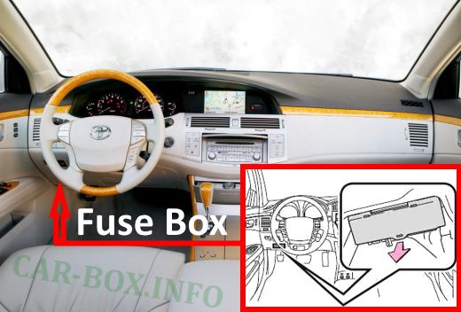
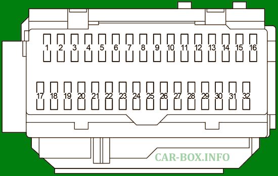
The fuse box is located on the driver’s side under the dashboard, behind a removable panel.
| Diagram | ||
|---|---|---|
|
||
| No. | Circuit Protected | A |
| 1 | 2005–2009: Power window (rear right) | 25 |
| 2010–2012: Power window (rear right) | 20 | |
| 2 | 2005–2009: Power window (rear left) | 25 |
| 2010–2012: Power window (rear left) | 20 | |
| 3 | 2005–2009: Power window (front passenger), driver position memory system | 25 |
| 2010–2012: Power window (front passenger), driver position memory system | 20 | |
| 4 | Front fog lamps | 15 |
| 5 | On-Board Diagnostics (OBD) system | 7.5 |
| 6 | Multiplex communication system | 7.5 |
| 7 | Empty | - |
| 8 | 2005–2009: Driver position memory system | 25 |
| 2010–2012: Power windows, driver position memory system | 20 | |
| 9 | Fuel filler door release | 7.5 |
| 10 | Multiport fuel injection system / sequential multiport fuel injection system, starting system, ignition system | 7.5 |
| 11 | Air conditioning system | 7.5 |
| 12 | 2008–2012: Air conditioning system | 20 |
| 13 | Multiplex communication system | 25 |
| 14 | Power moonroof | 30 |
| 15 | Parking lights, license plate lights, taillights, front and rear side marker lights | 10 |
| 16 | Heated seats, navigation system, hazard warning flashers, electronically controlled transmission, glove box light, instrument cluster lighting, power outlets | 7.5 |
| 17 | 2005–2006: Center display, shift lock control system, power moonroof, multiplex communication system | 7.5 |
| 2007–2012: Center display, shift lock control system, power moonroof, multiplex communication system, Tire Pressure Monitoring System (TPMS) | 10 | |
| 18 | Anti-lock braking system (ABS), Dynamic Laser Cruise Control, automatic headlight leveling system, Vehicle Stability Control (VSC) system, multiplex communication system | 7.5 |
| 19 | Air conditioning system, instrument cluster lighting, electric cooling fan | 7.5 |
| 20 | Air conditioning system | 7.5 |
| 21 | 2005–2007: Air conditioning system | 20 |
| 22 | Backup lamps, navigation system, turn signal flashers | 10 |
| 23 | Windshield wipers | 30 |
| 24 | Power rear sunshade | 10 |
| 25 | Not used | - |
| 26 | Multiport fuel injection system / sequential multiport fuel injection system, engine immobilizer system, Supplemental Restraint System (SRS), occupant detection system, Smart Key system, starter | 10 |
| 27 | Gauges and meters, center display | 7.5 |
| 28 | Power mirrors, center display, shift lock control system, multiplex communication system | 7.5 |
| 29 | Cigarette lighter | 15 |
| 30 | Power outlet | 15 |
| 31 | Audio system | 7.5 |
| 32 | Heated outside mirrors | 10 |
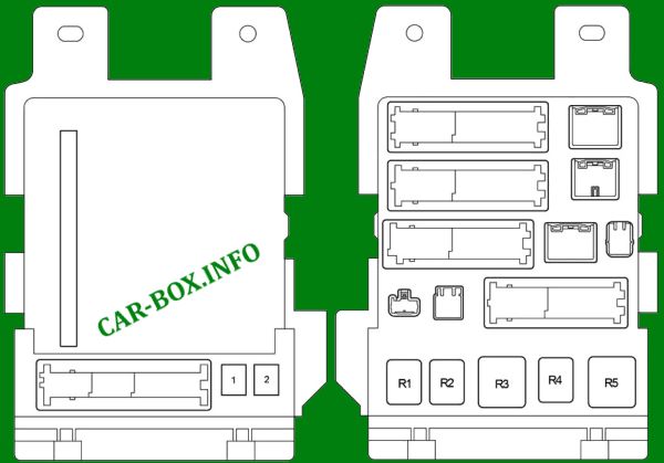
| Reverse side fuse block diagram | ||
|
||
| No. | Circuit Protected | A |
| 1 | Power seat | 30 |
| 2 | Power windows | 30 |
| Relays | ||
| R1 | Front fog lamps | |
| R2 | Tail lamps | |
| R3 | Auxiliary relay (ACC) | |
| R4 | Power relay (PWR) | |
| R5 | Ignition relay (IG1) | |
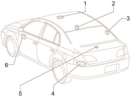
Body Electrical Components
Component locations:
|
|
| No. | Module |
| 1 | Sliding Roof Control ECU |
| 2 | Outer Mirror Control ECU (RH) |
| 3 | Door Control Receiver |
| 4 | Navigation ECU |
| 5 | Rear Sunshade Relay |
| 6 | Outer Mirror Control ECU (LH) |
