
This guide provides detailed fuse and relay box diagrams for first-generation Toyota Aygo (chassis code AB10; B-Zero platform) models produced from 2005, 2006, 2007, 2008, 2009, 2010, 2011, 2012, 2013, 2014 in both left-hand drive (LHD) and right-hand drive (RHD) configurations.
Below you will find the locations, photos, and circuit assignments for the fuse blocks. The cigarette lighter fuse is highlighted in bold.
In the engine compartment
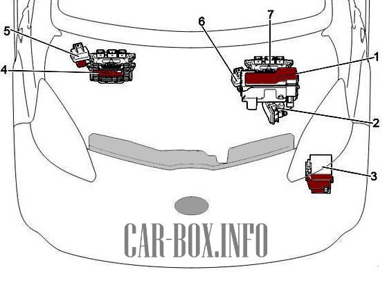
General component layout.
|
|
| 1 | Engine compartment fuse box |
| 2 | ABS / Traction control module |
| 3 | Relay box |
| 4 | Left-hand drive : Engine Control Module (ECM) |
| 5 | Left-hand drive : Glow plug relay |
| 6 | Right-hand drive : Glow plug relay |
| 7 | Right-hand drive : Engine Control Module (ECM) |
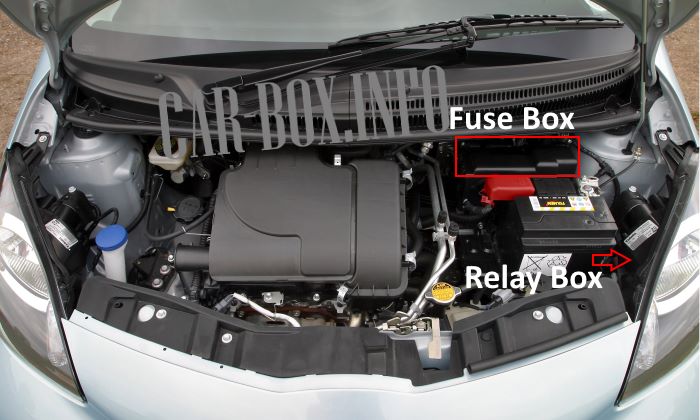
The main fuse box is located near the battery towards the windshield cowl. The auxiliary relay box is located below the headlight assembly.
Fuse box
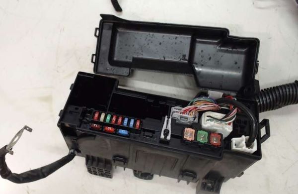
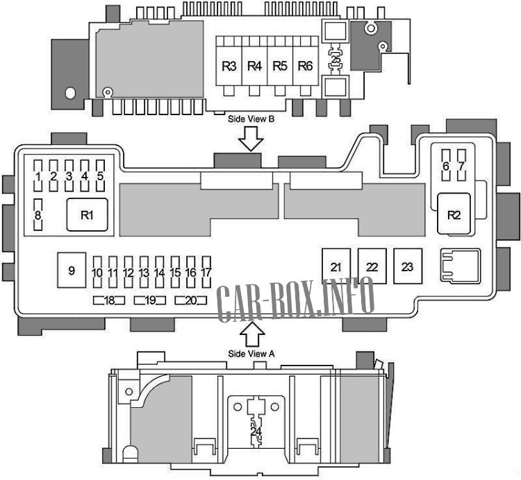
Main fuse box layout.
| Diagram | ||
|---|---|---|
|
||
| No. | Description | A |
| 1 | EFI 4 — 2WZ-TV engine: Sequential multiport fuel injection system | 15 |
| 2 | H-LP RH (HI) — Up to Feb 2012: Right headlight (high beam) | 10 |
| DRL — From Feb 2012: Daytime running lights | 5 | |
| 3 | H-LP LH (HI) — Up to Feb 2012: Left headlight (high beam), sensors, instrument cluster | 10 |
| FR FOG — From Feb 2012: Front fog lights | 20 | |
| 4 | H-LP RH (LO) — Up to Feb 2012: Right headlight (low beam) | 10 |
| H-LP LH — From Feb 2012: Left headlight | 10 | |
| 5 | H-LP LH (LO) — Up to Feb 2012: Left headlight (low beam), sensors, instrument cluster | 10 |
| H-LP RH — From Feb 2012: Right headlight | 10 | |
| 6 | STA — 1KR-FE engine: Multi-Mode Manual Transmission (MMT), sequential multiport fuel injection system | 7.5 |
| FAN #2 — 2WZ-TV engine: Radiator cooling fan | 7.5 | |
| 7 | EFI #2 — Sequential multiport fuel injection system, Multi-Mode Manual Transmission (MMT) | 7.5 |
| 8 | EFI #3 — 2WZ-TV engine: Multiport fuel injection, radiator cooling fan | 10 |
| MET — Sensors and instrument cluster | 5 | |
| 9 | AMT — 1KR-FE engine: Multi-Mode Manual Transmission (MMT) | 50 |
| RADIATOR FAN — 2WZ-TV engine: Radiator cooling fan | 50 | |
| 10 | H-LP LH — Without DRL: Left headlight | 10 |
| Up to Feb 2012: DIMMER — with DRL: fuses “H-LP LH (HI)”, “H-LP RH (HI)”, “H-LP LH (LO)”, “H-LP RH (LO)”, daytime running light system | 10 | |
| From Feb 2012: SUB-LP — with DRL: fuses “DRL”, “FR FOG” | 10 | |
| 11 | VSC #2 — Anti-lock Braking System (ABS), Vehicle Stability Control (VSC) | 30 |
| ABS #2 — Without VSC: Anti-lock Braking System (ABS) | 25 | |
| 12 | AM2 — Ignition/starting system, fuses “IG1”, “IG2”, “STA” | 30 |
| 13 | HAZARD — Turn signal lights, hazard warning flashers, instrument cluster | 10 |
| 14 | H-LP RH — Up to Feb 2012: Right headlight | 10 |
| H-LP MAIN — From Feb 2012: fuses “H-LP LH”, “H-LP RH” | 20 | |
| 15 | DOME — Instrument cluster, interior lighting, audio system, tachometer | 15 |
| 16 | EFI — 1KR-FE engine: Radiator cooling fan, multiport fuel injection | 15 |
| EFI — 2WZ-TV engine: Radiator cooling fan, multiport fuel injection | 25 | |
| 17 | HORN — Horn | 10 |
| 18 | Spare | 7.5 |
| 19 | Spare | 10 |
| 20 | Spare | 15 |
| 21 | RADIATOR — Hot climate spec: Radiator cooling fan | 40 |
| RADIATOR — Standard spec: Radiator cooling fan | 30 | |
| 22 | VSC1 — Anti-lock Braking System (ABS), Vehicle Stability Control (VSC) | 50 |
| ABS1 — Without VSC: Anti-lock Braking System (ABS) | 40 | |
| 23 | EMPS — Electric Power Steering (EPS) | 50 |
| 24 | ALTERNATOR — 1KR-FE engine: Charging system, fuses “EPS”, “ABS” (without VSC), “VSC” (with VSC), “RADIATOR”, “AM1”, “HTR”, “PWR”, “D/L”, “DEF”, “TAIL”, “STOP”, “OBD”, “ECU-B” | 120 |
| 25 | EBD resistor | |
| Relay Assignments | ||
| R1 | A/C MAG — Air conditioning magnetic clutch | |
| R2 | ST — Starter motor | |
| R3 | EFI MAIN — Engine Control Module (ECM) | |
| R4 | 1KR-FE engine: Circuit Opening / Fuel Pump Relay (C/OPN) | |
| R5 | Horn relay | |
| R6 | Radiator cooling fan No. 1 | |
Relay box
Located below the headlight assembly.
| Diagram | ||
|---|---|---|

|
||
| No. | Relay | |
| R1 | PTC heater No. 1 | |
| R2 | PTC heater No. 2 | |
| R3 | Unused | |
| R4 |
|
|
| R5 | Dimmer (DIM) | |
| No. | Fuse | A |
| 1 | Unused | - |
| 2 | PTC2 - PTC heater | 80 |
| 3 | PTC1 - PTC heater | 80 |
In the passenger compartment
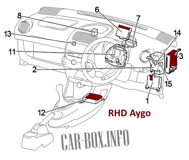
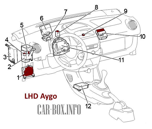
General component layout.
|
|
|
|
| No. | Component |
| 1 | Electric Power Steering (EPS) ECU |
| 2 | Junction connector |
| 3 | Multi-Mode Manual Transmission (MMT) ECU |
| 4 | Power window relay |
| 5 | Left-hand drive models: |
| Up to Feb 2012: Tail lamp relay | |
| From Feb 2012: Rear fog lamp relay | |
| 6 | Door control module with wireless receiver |
| 7 | Relay block No. 1 |
| 8 | Air conditioning amplifier |
| 9 | Left-hand drive: Front fog lamp relay |
| 10 | Left-hand drive: Clearance/position lamp relay |
| 11 | Fuse box |
| 12 | Airbag sensor assembly center |
| 13 | Right-hand drive: Relay block No. 2 |
| 14 | Right-hand drive models: |
| Up to Feb 2012: Ignition (IG) relay | |
| From Feb 2012: Power window relay | |
| 15 | Right-hand drive models: |
| Up to Feb 2012: Power window relay | |
| From Feb 2012: Rear fog lamp relay | |
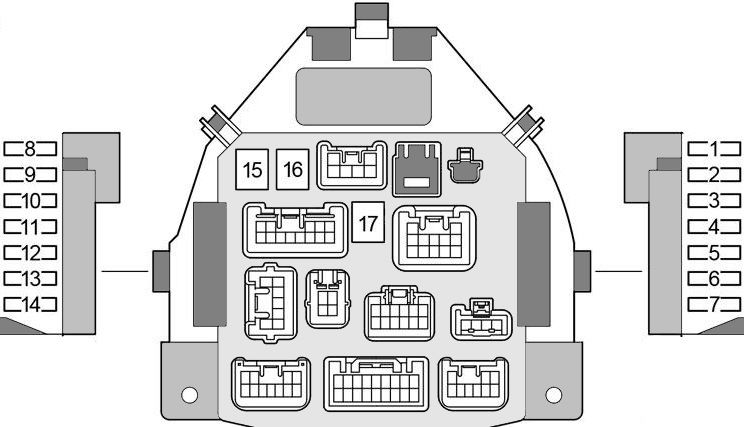
Fuse box

Passenger compartment fuses are located behind instrument panel covers on both sides of the speedometer assembly.

To access the fuse box, remove the three mounting screws located behind the steering wheel (rotate the steering wheel side to side for screwdriver access).
| Diagram | ||
|---|---|---|
|
||
| No. | Function / Circuit | A |
| 1 | STOP — Stop lamps, high-mounted stop lamp, Anti-lock Braking System (ABS), Multi-Mode Manual Transmission (MMT) | 10 |
| 2 | D/L — Power door lock system, wireless remote control system | 25 |
| 3 | DEF — Rear window defogger | 20 |
| 4 | TAIL — Daytime running lights, tail lamps, license plate lamps, side marker lamps, headlight leveling system, instrument panel illumination | 7.5 |
| 5 | OBD — On-board diagnostics system | 7.5 |
| 6 | ECU-B — Multi-Mode Manual Transmission (MMT), daytime running lights, Vehicle Stability Control (VSC), instrument cluster, rear fog lamp | 7.5 |
| 7 | Unused | |
| 8 | ECU-IG — Anti-lock Braking System (ABS), Vehicle Stability Control (VSC), Electric Power Steering (EPS), radiator cooling fan | 7.5 |
| 9 | BACK UP — Backup lamps, power door locks, wireless remote control, power windows, rear window defogger, tachometer, air conditioning system, heater | 10 |
| 10 | WIP — Windshield wiper and washer, rear window wiper and washer | 20 |
| 11 | ACC — Toyota Aygo Cigarette Lighter Fuse, power outlet, audio system | 15 |
| 12 | IG1 — Windshield/rear wipers and washers, Anti-lock Braking System (ABS), Electric Power Steering (EPS), radiator cooling fan, backup lamps, power door locks, wireless remote control, power windows, rear window defogger, tachometer, air conditioning, heater | 7.5 |
| 13 | IG2 — Sequential multiport fuel injection system, SRS airbag system, instrument cluster, daytime running lights, Multi-Mode Manual Transmission (MMT) | 15 |
| 14 | A/C — Air conditioning system, heater | 7.5 |
| 15 | AM1 — Fuses “ACC”, “WIP”, “ECU-IG”, “BACK UP” | 40 |
| 16 | PWR — Power windows | 30 |
| 17 | HTR — Heater, air conditioning, fuse “A/C” | 40 |
Relay blocks
Relay assignment.
| Relay Block No. 1 | |
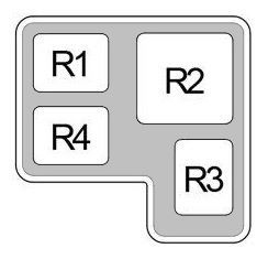
|
|
| R1 | Accessories (ACC) |
| R2 | Heater (HTR) |
| R3 | Rear window defogger (DEF) |
| R4 | Left-hand drive: Ignition (IG) |
| Relay Block No. 2 | |

|
|
| R1 | Ignition (IG) |
| R2 | Front fog lamps (FOG) |
