
The eighth-generation Toyota Hilux pickup debuted in 2015. Generational updates brought significant changes not only to the vehicle’s styling, but also to its underlying engineering: the Hilux received a brand-new frame and a redesigned suspension geometry. The exterior underwent extensive updates, featuring LED daytime running light strips in the headlights, smoothed wheel arch contours, newly shaped taillights, and chrome bumper trim. In the cabin, enhanced attention was paid to material quality and ergonomics. New powertrain options were introduced to the engine lineup. For instance, in Middle Eastern markets, a new 2.4-liter GD-series turbodiesel was offered alongside legacy engines, paired with either a manual transmission or a 6-speed Super ECT automatic transmission.
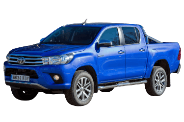
Most electrical circuits in this Japanese pickup truck are protected by fuses. High-current components—such as headlights, fan motors, and the fuel pump—are switched via relays. Fuses and relays are housed in junction/distribution boxes located in the passenger compartment and engine compartment. This article provides detailed fuse box diagrams and relay assignments for the 8th-generation Toyota Hilux (chassis codes AN120, AN130, GUN125, GUN126, GUN135, GUN136, GGN125, TGN121; Toyota IMV platform; 2015, 2016, 2017, 2018, 2019, and 2020 model years).
Engine Compartment
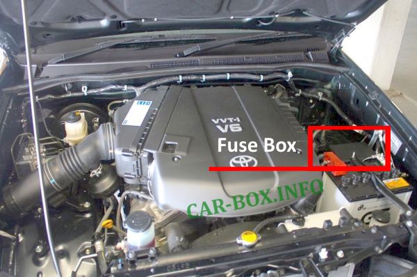
The fuse box is located on the left side of the engine compartment, adjacent to the battery.
| Diagram | ||
|---|---|---|
|
||
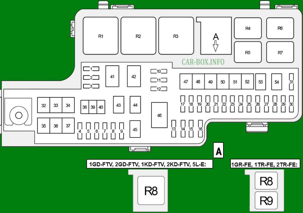
| No. | Description | A |
| 1 | Empty | - |
| 2 | Empty | - |
| 3 | Empty | - |
| 4 | Power outlet (inverter) | 20 |
| 5 | Double locking system | 10 |
| 6 | Empty | - |
| 7 | From Aug. 2017: Stop lamps, ABS, TRC, VSC, Multiport Fuel Injection system / Sequential Multiport Fuel Injection system, charging system, Downhill Assist Control, Smart Entry & Start system, Hill-start Assist Control, immobilizer system, shift lock, starter, steering lock, wireless door lock control | 10 |
| 8 | Up to Aug. 2017: Stop lamps, ABS, TRC, VSC, Multiport Fuel Injection system / Sequential Multiport Fuel Injection system, charging system, Downhill Assist Control, Smart Entry & Start system, Hill-start Assist Control, immobilizer system, shift lock, starter, steering lock, wireless door lock control | 10 |
| From Aug. 2017: Heated steering wheel | 10 | |
| 9 | 4WD control system | 10 |
| 10 | 4WD, Multiport Fuel Injection system / Sequential Multiport Fuel Injection system, ABS, automatic air conditioning, audio system, charging system, clock, combination meter, door lock control, double locking system, Downhill Assist Control, Smart Entry & Start system, headlights, automatic headlight leveling system, headlight washers, Hill-start Assist Control, illumination, immobilizer system, interior lights, key reminder, Lane Departure Alert, light reminder, navigation system, Pre-Collision System, rearview monitor, seat belt reminder, SRS airbag system, starter, steering lock, Stop & Start system, tail lamps, telematics system, security system, Tire Pressure Warning System, TRC, turn signals and hazard warning lights, VSC, wireless door lock control | 10 |
| 11 | Audio system, navigation system, rearview monitor | 20 |
| 12 | Immobilizer system, Smart Entry & Start system, interior lights, starter, steering lock, security system, wireless door lock control | 10 |
| 13 | Right headlight (low beam) | 10 |
| 14 | Left headlight (low beam), headlight leveling system, headlight washers | 10 |
| 15 | Right headlight (high beam) | 10 |
| 16 | Left headlight (high beam) | 10 |
| 17 | Security system | 7.5 |
| 18 | Telematics system | 7.5 |
| 19 | Buzzer, Smart Entry & Start system, immobilizer system, starter, steering lock, security system, wireless door lock control | 10 |
| 20 | Sequential Multiport Fuel Injection system (SFI) | 7.5 |
| 21 | Charging system | 7.5 |
| 22 | Smart Entry & Start system, immobilizer system, starter, steering lock, wireless door lock control | 7.5 |
| 23 | Automatic air conditioning, Multiport Fuel Injection system / Sequential Multiport Fuel Injection system, Smart Entry & Start system, immobilizer system, mirror heater, multiplex communication system, starter, steering lock, security system, wireless door lock control | 10 |
| 24 | 1GR-FE, 1TR-FE, 2TR-FE: Air-fuel ratio sensor | 20 |
| 24 | 1GD-FTV, 2GD-FTV, 1KD-FTV, 2KD-FTV, 5L-E: Multiport Fuel Injection system / Sequential Multiport Fuel Injection system | 25 |
| 25 | Multiport Fuel Injection system / Sequential Multiport Fuel Injection system, Smart Entry & Start system, immobilizer system, starter, steering lock, wireless door lock control | 10 |
| 26 | 1GR-FE, 1TR-FE, 2TR-FE: Combination meter, Multiport Fuel Injection system / Sequential Multiport Fuel Injection system, ignition | 15 |
| 2GD-FTV with Stop & Start system: Smart Entry & Start system, immobilizer system, starter, steering lock, wireless door lock control | 30 | |
| 27 | Smart Entry & Start system, immobilizer system, starter, steering lock, wireless door lock control | 10 |
| 28 | Automatic light control, door lock control, Smart Entry & Start system, front fog lamps, headlights, illumination, immobilizer system, interior lights, power windows, rear fog lamp, starter, steering lock, tail lamps, security system, wireless door lock control | 25 |
| 29 | Empty | - |
| 30 | “ECU-B NO.1”, “RADIO”, “DOME” fuses | 30 |
| 31 | Occupant detection ECU | 7.5 |
| 32 | Up to Aug. 2017: Power seat | 30 |
| From Aug. 2017: Power seat | 30 | |
| 33 | PTC heater | 30 |
| 34 | Empty | - |
| 35 | ABS, TRC, VSC, Downhill Assist Control, Hill-start Assist Control | 50 |
| 36 | 30 | |
| 37 | “IG1 NO.2” relay: “4WD-IG”, “S / HTR”, “S / HTR / S / VENT”, “IG1 NO.5” fuses | 30 |
| 38 | Empty | - |
| 39 | Empty | - |
| 40 | PTC heater | 50 |
| 41 | Glow plug system | 80 |
| 42 | “EFI-MAIN NO.1”, “EFI-MAIN NO.2”, “TURN & HAZ”, “ETCS”, “EFI NO.1”, “AM2 NO.2” relays and fuses | 60 |
| 43 | Headlight cleaners | 30 |
| 45 | “DEF” relay; “DEF”, “FOG RR”, “DEICER”, “DEF-S” fuses | 50 |
| 46 | “P / W”, “ACC” relays; “R / B FLOOR-ALT”, “R / B I / P-ALT”, “4WD-ALT”, “INV”, “ABS NO. 1”, “ABS NO. 2”, “STOP”, “P / SEAT”, “P / SEAT (D)”, “H-LP CLN”, “STRG HTR”, “ECU-ALT NO. 1”, “PTC HTR NO. 1”, “PTC HTR NO. 2”, “CDS FAN / PTC HTR NO. 3”, “HTR”, “DOOR R / L”, “DOOR NO. 1”, “DOOR R / R”, “DOOR NO. 2”, “FOG FR / DRL”, “TAIL”, “OBD”, “ECU-ALT NO. 2”, “AM1”, “P / OUTLET NO. 1”, “SFT LOCK-ACC” fuses | 140 |
| 47 | Stop & Start system | 40 |
| 48 | Empty | - |
| 49 | Stop & Start system | 40 |
| 50 | 1GR-FE, 1TR-FE, 2TR-FE: Smart Entry & Start system, immobilizer system, starter, steering lock, wireless door lock control | 30 |
| 1GD-FTV, 2GD-FTV, 1KD-FTV, 2KD-FTV, 5L-E: Smart Entry & Start system, immobilizer system, starter, steering lock, wireless door lock control | 50 | |
| 51 | Empty | - |
| 52 | Empty | - |
| 53 | Secondary air injection pump | 50 |
| “DCU-MAIN” relay; “DCU NO.1”, “DCU NO.2”, “DCU-B”, “NOX PM” fuses | 50 | |
| 54 | “H-LP”, “DIMMER” relays; “H-LP LH-LO”, “H-LP RH-LO”, “H-LP LH-HI”, “H-LP RH-HI” fuses | 40 |
| No. | Relay | |
| R1 | Dimmer | |
| R2 | Headlight (H-LP) | |
| R3 | 1GD-FTV, 2GD-FTV, 1KD-FTV, 2KD-FTV, 5L-E: Starter (ST NO.1) | |
| R4 | 1GR-FE, 1TR-FE, 2TR-FE: Starter (ST NO.1) | |
| 2GD-FTV with Stop & Start system: Starter (ST NO.2) | ||
| R5 | Stop lamps / Electric cooling fan (STOP / CDS FAN) | |
| R6 | 1GR-FE, 1TR-FE, 2TR-FE: Fuel injector (INJ) | |
| 1GD-FTV, 2GD-FTV, 1KD-FTV, 2KD-FTV, 5L-E: Injector driver (EDU) | ||
| R7 | Horn | |
| R8 | 1GD-FTV, 2GD-FTV, 1KD-FTV, 2KD-FTV, 5L-E: Glow plug system (GLOW) | |
| 1GR-FE, 1TR-FE, 2TR-FE: Fuel pump / Air pump heater (FUEL PMP / AIR PMP HTR) | ||
| R9 | 1GR-FE, 1TR-FE, 2TR-FE: Air-fuel ratio sensor heater (A / F HTR) | |
Passenger Compartment
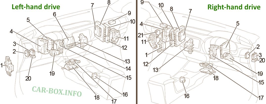
General layout of electronic control modules.
| No. | Component / Unit |
| 1 | Relay and fuse box No. 1 |
| 2 | Headlight leveling ECU |
| 3 | Central gateway ECU |
| 4 | Main fuse box |
| 5 | Stop & Start ECU |
| 6 | Telematics transceiver |
| 7 | 4WD control ECU |
| 8 | Engine Control Module (ECM) |
| 9 | Smart door control receiver (with Smart Entry & Start system), door control receiver (without Smart Entry & Start system) |
| 10 | Transmission Control Module (TCM) |
| 11 | Relay box No. 2 |
| 12 | Turbocharger driver |
| 13 | Relay box No. 3 |
| 14 | Navigation ECU |
| 15 | Relay box No. 4 |
| 16 | Shift lock ECU |
| 17 | Air conditioning amplifier |
| 18 | Airbag sensor assembly |
| 19 | Steering lock actuator |
| 20 | Junction connector |
Main Fuse Box
Located under the dashboard on the driver’s side (indicated by No. 4 in the component layout).
Access procedure:
RHD: Remove the lower instrument panel cover (if equipped), then remove the fuse box cover.
LHD: Remove the fuse box cover.
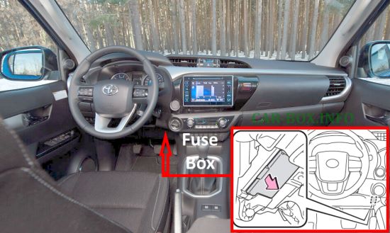
Location photo (LHD)
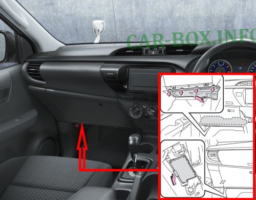
Location photo (RHD)
| Diagram | ||
|---|---|---|
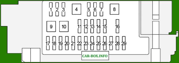
|
||
| No. | Description | A |
| 1 | Power windows | 25 |
| 2 | 25 | |
| 3 | 25 | |
| 4 | 30 | |
| 5 | 1GR-FE, 1KD-FTV, 2KD-FTV, 1TR-FE, 2TR-FE, 5L-E: Multiport Fuel Injection system / Sequential Multiport Fuel Injection system | 10 |
| 1GD-FTV, 2GD-FTV: ABS, A/C, Downhill Assist Control, Multiport Fuel Injection system / Sequential Multiport Fuel Injection system, Hill-start Assist Control, TRC, VSC | 25 | |
| 6 | 1GR-FE, 1KD-FTV, 2KD-FTV, 1TR-FE, 2TR-FE, 5L-E: ABS, A/C, Downhill Assist Control, Multiport Fuel Injection system / Sequential Multiport Fuel Injection system, Hill-start Assist Control, TRC, VSC | 25 |
| 1GD-FTV, 2GD-FTV: Multiport Fuel Injection system / Sequential Multiport Fuel Injection system | 25 | |
| 7 | Turn signals and hazard warning lights, combination meter, door lock control, Smart Entry & Start system, immobilizer system, starter, steering lock, security system, wireless door lock control | 10 |
| 8 | Multiport Fuel Injection system / Sequential Multiport Fuel Injection system, Smart Entry & Start system, immobilizer system, starter, steering lock, wireless door lock control | 30 |
| 9 | Air conditioning, charging system | 40 |
| 10 | Smart Entry & Start system, immobilizer system, starter, steering lock, wireless door lock control | 40 |
| 11 | 1GR-FE, 1KD-FTV, 2KD-FTV, 1TR-FE, 2TR-FE, 5L-E: Tail lamps, illumination, automatic light control, charging system, Smart Entry & Start system, front fog lamps, immobilizer system, key reminder, light reminder, rear fog lamp, starter, steering lock, wireless door lock control | 10 |
| 1GD-FTV, 2GD-FTV: Door lock control, power windows, security system | 10 | |
| 12 | Front fog lamps, headlights, illumination, tail lamps | 10 |
| 13 | 1GR-FE, 1KD-FTV, 2KD-FTV, 1TR-FE, 2TR-FE, 5L-E: Door lock control, power windows, security system | 10 |
| 1GD-FTV, 2GD-FTV: Tail lamps, illumination, automatic light control, charging system, Smart Entry & Start system, front fog lamps, immobilizer system, key reminder, light reminder, rear fog lamp, starter, steering lock, wireless door lock control | 10 | |
| 14 | On-board diagnostics system (OBD) | 10 |
| 15 | ABS, air conditioning, Downhill Assist Control, Multiport Fuel Injection system / Sequential Multiport Fuel Injection system, Hill-start Assist Control, Stop & Start system, TRC, VSC | 10 |
| 16 | Multiport Fuel Injection system / Sequential Multiport Fuel Injection system | 5 |
| 17 | Combination meter, 4WD, ABS, automatic air conditioning, audio system, charging system, door lock control, Downhill Assist Control, Multiport Fuel Injection system / Sequential Multiport Fuel Injection system, Smart Entry & Start system, headlights, automatic headlight leveling system, headlight washers, Hill-start Assist Control, illumination, immobilizer system, interior lights, key reminder, Lane Departure Alert, light reminder, navigation system, Pre-Collision System, rearview monitor, seat belt reminder, SRS airbag system, starter, steering lock, Stop & Start system, tail lamps, telematics system, security system, Tire Pressure Warning System, TRC, turn signals and hazard warning lights, VSC, wireless door lock control | 5 |
| 18 | SRS airbag system | 5 |
| 19 | Charging system, Multiport Fuel Injection system / Sequential Multiport Fuel Injection system, immobilizer system, multiplex communication system, telematics system | 5 |
| 20 | Shift lock | 10 |
| 21 | Power outlets, cigarette lighter | 15 |
| 22 | Smart Entry & Start system, immobilizer system, starter, steering lock, wireless door lock control | 5 |
| 23 | Front wiper and washer | 25 |
| 24 | Audio system, back-up lamps, charging system, combination meter, Multiport Fuel Injection system / Sequential Multiport Fuel Injection system, Lane Departure Alert, navigation system, rearview monitor | 10 |
| 25 | Empty | - |
| 26 | ABS, Downhill Assist Control, Hill-start Assist Control, Stop & Start system, TRC, VSC | 10 |
| 27 | Air conditioning, audio system, automatic light control, charging system, combination meter, door lock control, Multiport Fuel Injection system / Sequential Multiport Fuel Injection system, Smart Entry & Start system, front fog lamps, headlights, automatic headlight leveling system, headlight washers, illumination, immobilizer system, interior lights, mirror heaters, multiplex communication system, navigation system, power outlet, power windows, rear fog lamp, rearview monitor, rear window defogger, seat belt reminder, SRS airbag system, starter, steering lock, Stop & Start system, tail lamps, security system, Tire Pressure Warning System, wireless door lock control | 10 |
| 28 | Front wiper and washer | 15 |
| 29 | Charging system, shift lock | 10 |
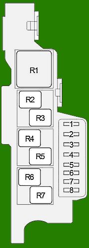
Auxiliary Fuse Box No. 1
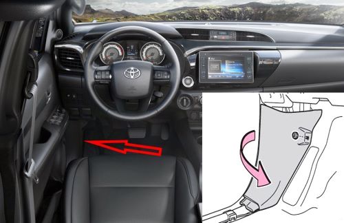
Located on the driver’s side, behind the cowl side trim.
| Diagram | ||
|---|---|---|
|
||
| No. | Description | A |
| 1 | Dosing control unit (DCU) ECU | 25 |
| 2 | 20 | |
| 3 | NOx sensor | 20 |
| 4 | Dosing control unit (DCU) ECU | 7.5 |
| 5 | Mirror heaters, Sequential Multiport Fuel Injection system | 10 |
| 6 | Rear fog lamps | 10 |
| 7 | Windshield wiper de-icer | 15 |
| 8 | Rear window defogger, mirror heaters, Sequential Multiport Fuel Injection system | 25 |
| No. | Relay | |
| R1 | Dosing control unit main relay (DCU-MAIN) | |
| R2 | NOx sensor (NOX PM) | |
| R3 | Windshield wiper de-icer (DEICER) | |
| R4 | Rear fog lamps (FOG RR) | |
| R5 | Empty | |
| R6 | Inverter (INV) | |
| R7 | Rear window defogger, mirror heaters (DEF) | |
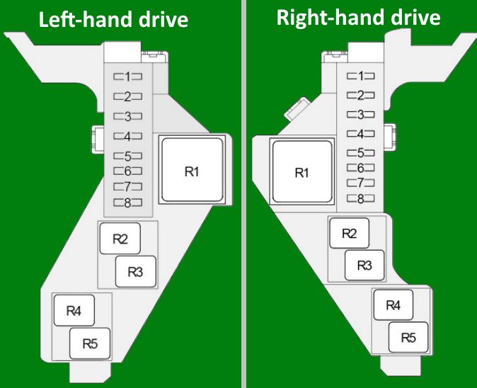
Auxiliary Fuse Box No. 2

Located on the passenger side.
| Diagram | ||
|---|---|---|
|
||
| No. | Function | A |
| 1 | 4WD, ABS, air conditioning, audio system, charging system, clock, combination meter, door lock control, Downhill Assist Control, Multiport Fuel Injection system / Sequential Multiport Fuel Injection system, Smart Entry & Start system, headlights, automatic headlight leveling system, headlight washers, Hill-start Assist Control, illumination, immobilizer system, interior lights, key reminder, Lane Departure Alert, light reminder, multiplex communication system, navigation system, Pre-Collision System, rearview monitor, power mirrors, seat belt reminder, SRS airbag system, starter, steering lock, Stop & Start system, tail lamps, telematics system, security system, Tire Pressure Warning System, TRC, turn signals and hazard warning lights, VSC, wireless door lock control | 5 |
| 2 | Manual air conditioning | 10 |
| 3 | Multiport Fuel Injection system / Sequential Multiport Fuel Injection system | 10 |
| 4 | Starter, Multiport Fuel Injection system / Sequential Multiport Fuel Injection system | 7.5 |
| 5 | Empty | - |
| 6 | 4WD system | 20 |
| 7 | Heated seats | 15 |
| 8 | Air conditioning, Lane Departure Alert, Pre-Collision System | 10 |
| No. | Relay | |
| R1 | Heater blower (HTR) | |
| R2 | Ignition (IG1 NO. 2) | |
| R3 | Ignition (IG2) | |
| R4 | Heated steering wheel (STRG HTR) | |
| R5 | Air conditioning magnetic clutch (A / C COMP) | |
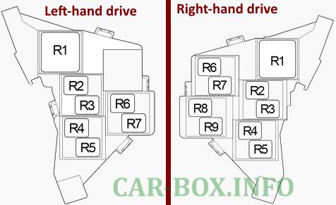
Relay Box No. 3
Indicated by No. 13 in the interior component layout.
|
|
| No. | Function |
| R1 | PTC heater (PTC HTR) |
| R2 | |
| R3 | |
| R4 | Viscous heater (VISCOUS) |
| R5 | Empty |
| R6 | Door lock (D / L NO. 1) |
| R7 | Door lock (D / L NO. 2) |
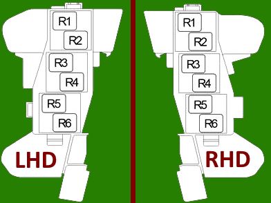
Relay Box No. 4
Indicated by No. 15 in the interior component layout.
|
|
| No. | Function |
| R1 | Daytime running lights (DRL) |
| R2 | Security horn (S-HORN) |
| R3 | Front fog lamps (FOG FR) |
| R4 | Tail lamps (TAIL) |
| R5 | Interior illumination cut-off (DOME CUT) |
| R6 | Ignition (IG1 NO. 1) |

Good day, I seems confused? which fuse number is for the car radio not turning on?
thank you