Toyota Gaia is a five-door, six- or seven-seater minivan. The base for this car is the Ipsum model - Sistercar. In this regard, the body models of both Ipsum and Gaia are identical - the body (front-wheel drive models): SXM 10G, CXM 10G, ACM 10G and the body (all-wheel drive models): SXM 15G, CXM 15G, ACM 15G. In this article, we will take a detailed look at the fuse box diagrams for the Toyota Gaia 1st generation (XM10) 1998, 1999, 2000, 2001, 2002, 2003, 2004 release.

Here you will find the locations and photos of distribution boxes. The fuses responsible for the “Cigarette lighter” and “Fuel Pump” are highlighted in bold.
In the engine compartment
General layout of electrical equipment.

|
|
| 1 | ABS modulator (up to 04.2001), |
| 2 | modulator and ABS ECU (2WD, from 04.2001), |
| 3 | ABS modulator (4WD, from 04.2001), |
| 4 | vacuum sensor in the brake booster circuit (1AZ-FSE engine) |
| 5 | injector amplifier (1AZ-FSE engine), |
| 6 | relay block# 1 (except for the ZS-TE engine), |
| 7 | relay block #1 (engine ZS-TE), |
| 8 | SRS sensor |
| 9 | glow plug relay (engine ZS-TE), |
| 10 | fuse and relay box #1 |
| 11 | SRS sensor. |
Fuse box
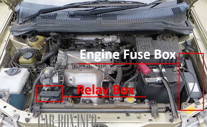
Located near the battery, behind a protective cover.

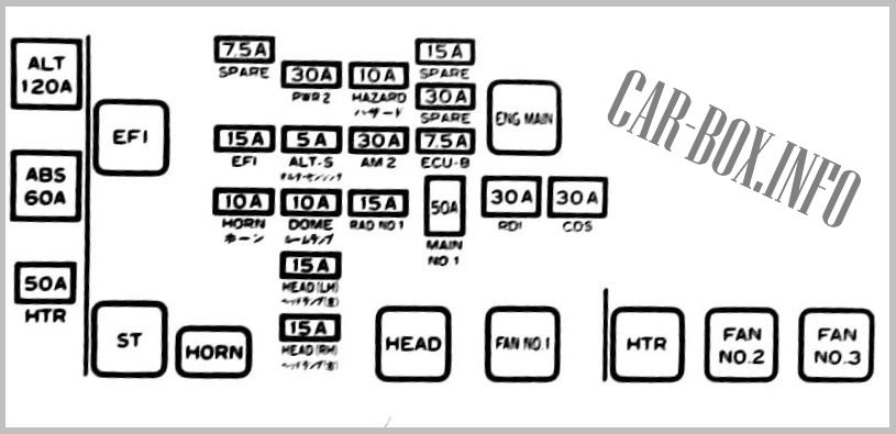
Photo - an example of the execution of the main unit.
| Diagram | ||
|---|---|---|
|
||
| No. | A | Description |
| AM2 | 30 | Egnition lock |
| AM 2, FUEL HTR |
30 | Ignition switch, fuel heater |
| RAD # 1 | 15 | Radio cassette |
| PWR 2 | 30 | Power windows in the driver's door |
| ALT-S | 5 | Generator |
| DOME | 10 | Interior lamps, local lamps, luggage compartment lamp, clock |
| HEAD (LH) |
15 | Headlamp (left) |
| HEAD (RH) |
15 | Headlamp (right) |
| EFI | 15 | Fuel injection system |
| HORN | 10 | Sound signal |
| HORN, HAZ |
15 | Sound signal, alarm |
| ACC SOCKET, PWR OUTLET |
15 | Power Outlet (trunk) |
| ALT | 120 | Generator |
| HTR | 50 | Stove heater |
| ABS | 60 | ABS system |
| EFI | - | Injection system relay |
| ST | - | Starter relay |
| HORN | - | Sound Signal relay |
| HEAD | - | Headlamp relay |
| ENG MAIN |
- | Main motor relay |
| FAN | - | Fan relay |
| HTR | - | Heater relay |
Relay box
An additional relay box is also located under the hood.
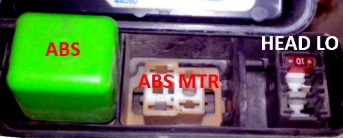
| Type 1 | |
|
|
| ABS | ABS system |
| ABS MTR | ABS motor relay |
| HEAD LO | Headlamps |
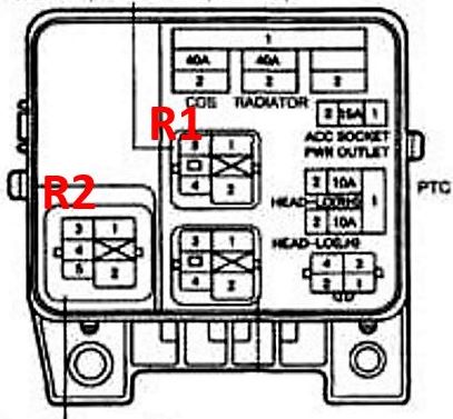
| Type 2 | |
|
|
| FAN2 | Cooling fan relay |
| ABS MTR | ABS motor system |
In the passenger compartment
General layout of electrical equipment.
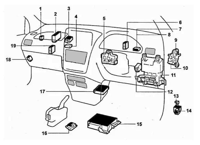
|
|
| No. | Component |
| 1 | Toyota Gaia fuel pump relay, |
| 2 | ECU engine, |
| 3 | remote control receiver for central locking (from 04.2001), |
| 4 | rear view camera control module (up to 04.2000), |
| 5 | central distribution box, |
| 6 | audio system amplifier (up to 04.2001), |
| 7 | TV tuner (up to 04.2000), |
| 8 | rear view camera control module (since 04.2001), |
| 9 | relay box No. 1 (R / B No. 1), |
| 10 | rear heater relay, |
| 11 | fuse box under the dash, |
| 12 | central locking relay (up to 04.2001), |
| 13 | relay board at the bottom of the A-pillar, |
| 14 | ACC relay, |
| 15 | CD changer (up to 04.2001), |
| 16 | deceleration sensor, |
| 17 | SRS control module, |
| 18 | parking system control module, |
| 19 | ABS and 4WD ECU, ABS ECU (2WD, up to 04.2001). |
Fuse box
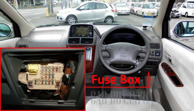
Located on the driver's side, at the bottom of the dashboard. To access it, you need to remove the glove box.

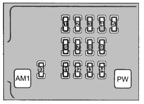
General view of the distribution box.
| Diagram | ||
|---|---|---|
|
||
| No. | Description | A |
| 1 | Turn Signal / Flasher (TURN) | 7.5 |
| 2 | ECU engine (IDLE UP) | 7.5 |
| 3 | Door locks (DOOR) | 30 |
| 4 | ECU engine (STARTER) | 7.5 |
| 5 | Parking lamps, licence plate illumination (TAIL) | 10 |
| 6 | Wipers and washers (WIPER) | 20 |
| 7 | ABS, parking system, electronic control unit for all-wheel drive system (ECU-IG) | 10 |
| 8 | Air conditioning and heater (METER AC) | 15 |
| 9 | Stop lamps, additional stop lamp (STOP) | 15 |
| 10 | RADIO - Clock, radio, CD player, Toyota gaya cigarette lighter fuse, mirror control system | 15 |
| 11 | ECU engine IG | 7.5 |
| 12 | RR DEF - Heated rear window | thirty |
| 13 | RR HEATER - Rear heater | ten |
| 14 | FR FOG - Front fog lamps | 15 |
| AM | Power group contactor of ignition locks | 40 |
| PW | Power windows | 30 |
