Most of the electrical circuits in the electrical equipment of the Japanese minivan are protected by fuses. Powerful current consumers are connected via relays. Protective elements are installed in distribution boxes located in the engine compartment and passenger compartment.

The information on the diagrams is relevant for Toyota Ipsum cars 1996, 1997, 1998, 1999, 2000, 2001 of release with gasoline 3S-FE (2.0 l) and diesel ZS-TE (2.2 l) engines.
In the passenger compartment
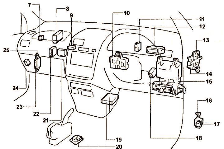
Location of components. 7 - fuel pump relay, 8 - engine control unit, 9 - rear view camera control unit, 10 - central distribution box, 11 - radio amplifier, 12 - TV receiver (from 08.97), 13 - relay block No. 1, 14 - relay rear heater, 15 - fuse block in the passenger compartment, 16 - relay box on the bulkhead of the engine compartment, 17 - auxiliary equipment power relay, 18 - central locking control relay, 19 - central airbag sensor, 20 - deceleration sensor (ABS), 21 - air conditioning amplifier, 22 - ABS control unit, 23 - fuse box, 24 - parking system control unit, 25 - connector bracket.
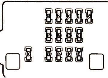
Fuse box
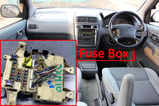
Located on the driver's side behind the glove compartment.
| Diagram | ||
|---|---|---|
|
||
| or | ||

|
||
| No. | Decoding | A |
| 1 | TURN - Turn signal lamps / Flasher | 7.5 |
| 2 | IDLE UP - Electronic engine control unit | 7.5 |
| 3 | DOOR - Door locks | 30 |
| 4 | STARTER - Electronic engine control unit | 7.5 |
| 5 | TAIL - Parking lamps, room lamps | 10 |
| 6 | WIPER - Wipers and washers | 20 |
| 7 | ECU-IG - ABS, parking system, electronic control unit for all-wheel drive system | 10 |
| 8 | METER AC - Air conditioning and heater | 15 |
| 9 | Stop lamps, additional stop lamp | 15 |
| 10 | Clock, radio, CD player, ipsum cigarette lighter fuse, mirror control system | 15 |
| 11 | IG - Electronic engine control unit | 7.5 |
| 12 | RR DEF - Heated rear window | 30 |
| 13 | RR HEATER - Rear heater | 10 |
| 14 | FR FOG - Front fog lamps | 15 |
Relay box
#16 on the picture.
| Diagram |
|---|

|
In the engine compartment
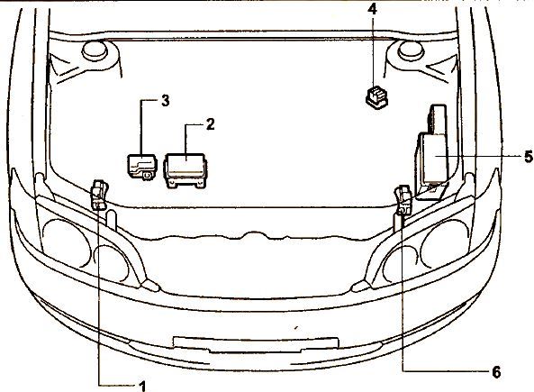
Location of components.
- right front SRS sensor,
- relay block #5 (ЗС-TE engine),
- relay block #5 (3S-FE engine),
- glow plug relay,
- main fuse block in the engine compartment, fuse block, block relay #2,
- left front SRS sensor,
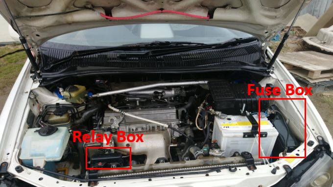
Photo location.
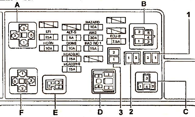
Fuse box
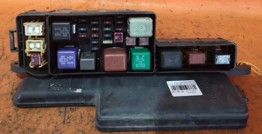
General view.
| Diagram | ||
|---|---|---|
|
||
| No. | Description | A |
| A | injection relay | |
| B | main motor relay | |
| C | radiator fan | |
| D | headlight relay | |
| E | horn relay | |
| F | starter relay | |
| 1 | CDS | 30 |
| 2 | RDI | 30 |
| 3 | MAIN | 30 |
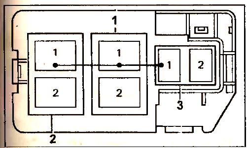
Relay box
#2 or #2 on the picture above.
| Diagram | ||
|---|---|---|
|
||
| 1 | ABS | 60 |
| 2 | ALT (generator) | 120 |
| 3 | HTR (heater) | 50 |
