The second generation Toyota Previa (Estima), which hit the market in 2000, leads the way among minivans. The previous generation of the model differed from the current traditional front-wheel drive. The new generation is equipped with all-wheel drive with active control. In this article, we will take a detailed look at the fuse diagrams for the Toyota Previa / Estima 2nd generation (XR30 / XR40) 2000, 2001, 2002, 2003, 2004, 2005, 2006 model year.

Here you will find the locations and photos of distribution boxes. The fuses responsible for the “Cigarette lighter” and “Fuel Pump” are highlighted in bold.
In the engine compartment
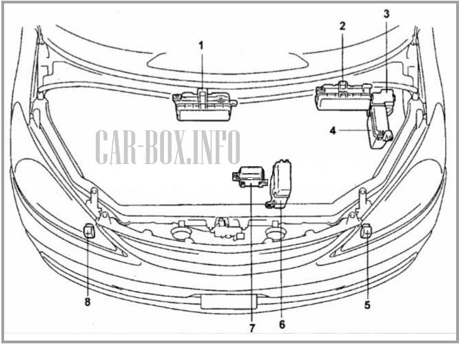
The layout of the distribution boxes in the engine compartment.
|
|
| No. | Component |
| 1 | Main fuse box (1MZ-FE engine) |
| 2 | Main fuse box (2AZ-FE engine) |
| 3 | Additional heater unit (2AZ-FE engine) |
| 4 | Power fuse board (2AZ-FE engine) |
| 5 | Left front SRS sensor |
| 6 | Power fuse board (1MZ-FE motor) |
| 7 | Fan motor relay unit (2AZ-FE engine) |
| 8 | right front SRS sensor. |
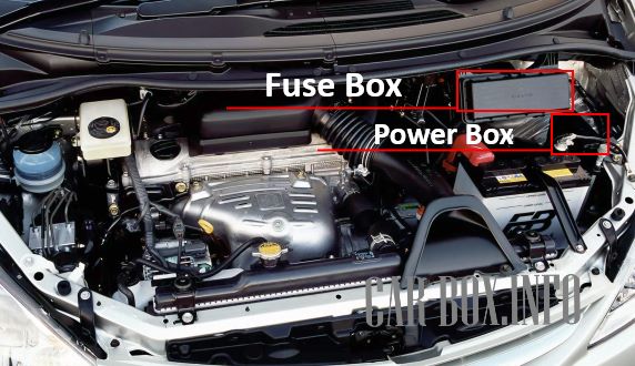
Photo of location (2AZ-FE engine).
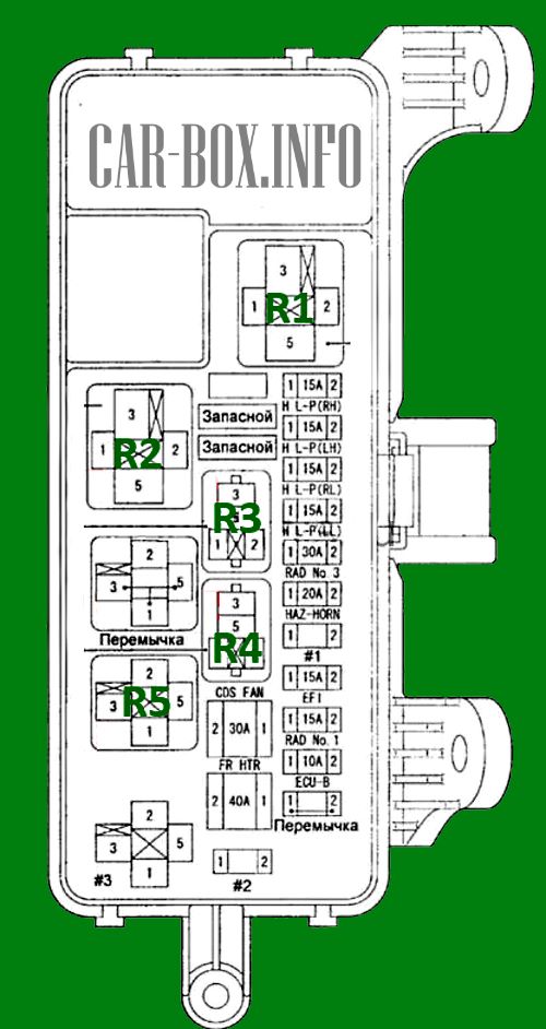
Fuse box

General view.
| Diagram | ||
|---|---|---|
|
||
| Code | Decoding of fuses | A |
| BLC | Automatic air conditioner (dual zone) | 10 |
| CDS FAN | Electric fan drive (models with 2AZ-FE engine) | 30 |
| RAD # 1 | Audio system | 15 |
| Rear LCD | ||
| Multivision system | ||
| RAD # 3 | Audio System (Multivision System) (10 Speaker Models) and Rear LCD | 30 |
| DOME | Interior lamps, ignition lock lighting | 10 |
| CURTAIN RH | Electric shutters | 15 |
| ECU-B | Engine management system, electronic control system of automatic transmission and immobilizer system | 10 |
| Anti-lock braking system | ||
| TEMS system | ||
| Switching indication | ||
| Sliding door electric drive | ||
| Electric rear door | ||
| Rear door closing aid | ||
| central locking | ||
| Power windows | ||
| The warning system about the left in the ignition switch and the switched off lighting | ||
| Multiplex system | ||
| Electric sunroof | ||
| Instrument cluster | ||
| Audio system | ||
| Rear LCD | ||
| Multivision system | ||
| Reversing lamps | ||
| Interior lamps | ||
| Automatic air conditioner (dual zone) | ||
| Speed Keeping System | ||
| HAZ-HORN | Sound signal | 20 |
| Turn signal lamps and hazard warning lamps (flasher) | ||
| H-LP (LH) | Headlamps (left, hight beam) | 15 |
| H-LP (LL) | Headlamps (left, low beam) | 15 |
| H-LP (RH) | Headlamps (models with xenon headlights) (right, hight beam) | 15 |
| H-LP (RL) | Headlamps (models with xenon headlights) (right, low beam) | 15 |
| PTC1 | Automatic air conditioner (dual zone) | 50 |
| PTC2 | 50 | |
| PTC3 | 50 | |
| EFI | Engine management system, electronic control system of automatic transmission and immobilizer system | 15 |
| FR HTR | Automatic air conditioner (dual zone) | 40 |
| VSC | Anti-lock braking system (VSC models) | 40 |
| P / W RH | Power windows | 30 |
| CURTAIN | Electric shutters | 5 |
| R1 | Headlamps relay | |
| R2 | Rear heater relay | |
| R3 | A / C clutch relay | |
| R4 | Horn relay | |
| R5 | Main relay of the injection system | |
Power block

General view.
| Diagram | ||
|---|---|---|

|
||
| Code | Description | A |
| ABS | Anti-lock braking system (models without VSC) | 25 |
| Anti-lock braking system | 40 | |
| ALT | Charging system | 140 |
| Launch system | ||
| Marker lamps | ||
| Backlight | ||
| ALT-S | Charging system | 5 |
| AMI | External consumers | 100 |
| AM2 | Headlamps | 80 |
| AM 2-2 | Launch system | 30 |
| FAN | Fan electric drive | 50 |
| R1 | Fan relay | |
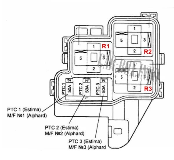
Additional heater block
Diagram.
|
|
| R1 | Relay for auxiliary heater |
| R2 | |
| R3 | |
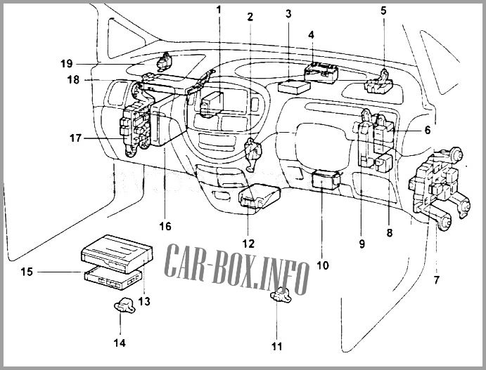
In the passenger comparment
General arrangement of electrical equipment.
|
|
| 1 | heater amplifier (models with air conditioning with manual control of release before 05.2003) |
| 2 | camera controller (models up to 05.2003) |
| 3 | camera controller (models from 05.2003 onwards) |
| 4 | central distribution box |
| 5 | electronic module of the parking system |
| 6 | electronic module of the cruise control system |
| 7 | driver side fuse box |
| 8 | buzzer |
| 9 | electronic ABS control module |
| 10 | air conditioning amplifier (models with manual air conditioning, manufactured before 05.2003) |
| 11 | lateral movement sensor and deceleration sensor (models up to 05.2003) |
| 12 | electronic control unit SRS |
| 13 | navigation system electronic unit |
| 14 | lateral movement sensor and deceleration sensor (models from 05.2003) |
| 15 | TV tuner (models 05.2001 - 05.2003) |
| 16 | Engine ECU |
| 17 | Passenger side fuse box |
| 18 | TV tuner (models up to 05.2001) |
| 19 | heater relay |
There are two blocks here - one behind the glove compartment on the driver's side and the other on the passenger's side.
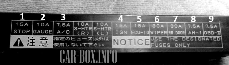
On the driver's side
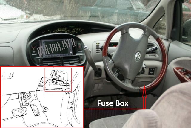
Photo - an example of block placement from the driver's side.
| Diagram | ||
|---|---|---|
|
||
| No. | Description | A |
| 1 | STOP - Stop lamps | 15 |
| 2 | GAUGE - Instrument panel, alarm | 10 |
| 3 | A / C - Air conditioner | 7.5 |
| 4 | IGN - SRS, ECT | 15 |
| 5 | ECU-IG - Multi AV-Station, cruise control | 15 |
| 6 | WIP - Windscreen wiper | 30 |
| 7 | CIG - Electric mirrors, cigarette lighter fuse preview / estima | 15/30 |
| 8 | AM1 - Power circuit relay | 7.5 |
| 9 | OBD II - Diagnostic connector | 7.5 |
On the passenger's side
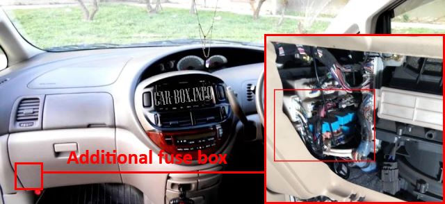
An additional block is located behind the glove compartment.
| Diagram | ||
|---|---|---|

|
||
| Code | Description | A |
| MET | Instrument cluster | 30 |
| TAIL (R) | Side lamps (right headlight) | 7.5 |
| FOG | Fog lamps | 15 |
| TAIL (L) | Side lamps (left headlight) | 7.5 |
| DEF | Heated rear window | 20 |
| PWE OUTLET |
Connector for additional equipment | 15 |
| T / M | Reversing lamps | 10 |
| l / UP | EATING | 10 |
| DOOR | Door drive | 30 |
| R1 | Main power relay | |
| R2 | Fog lamp relay | |
| R3 | Heated rear window relay | |
| R4 | ACC relay | |
| R5 | Fuel pump relay Toyota Previa / Estima | |
