
The Toyota FunCargo multi-purpose mini-MPV, based on the Toyota Vitz platform, debuted in 1999 as a compact yet versatile vehicle. It received a facelift three years later before being replaced by the Toyota Ractis in 2005. This article provides detailed fuse and relay box diagrams for the first-generation Toyota FunCargo (chassis code XP20; NBC platform) produced from 1999 to 2005.
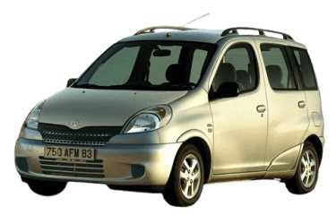
Here you will find component locations, photos, and diagrams for the electrical distribution boxes. Fuses for the “Cigarette Lighter” and “Fuel Pump” circuits are highlighted in bold.
Engine Compartment

There are four fuse and relay boxes located here:
- Fusible link block (on the battery terminal);
- Auxiliary relay box;
- Main fuse and relay box;
- ABS control module box (depending on equipment).
Main Fuse Box
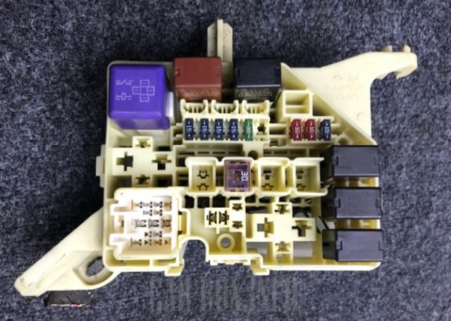
Photo: Example view of Main Fuse Box #3.
| Diagram | ||
|---|---|---|
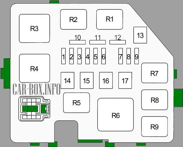
|
||
| No. | Circuit / Description | A |
| 1 | DOME - Digital clock, instrument cluster, central locking system, headlights, interior lamps, warning chime, multi-information display, audio system, power door lock ECU | 15 |
| 2 | EFI - Engine Control Module (ECM), engine immobilizer, Transmission Control Module (TCM) | 15 |
| 3 | HORN - Horn | 15 |
| 4 | AM2 - Charging system, instrument cluster, Engine Control Module (ECM), engine immobilizer, Transmission Control Module (TCM), multi-information display, SRS airbag system, ignition system | 15 |
| 5 | ST - Starter system | 30 |
| 6 | Unused | - |
| 7 | Headlight (Left), headlight leveling module | 10 |
| 8 | Headlight (Right), headlight leveling module | 10 |
| 9 | P / POINT - Auxiliary power outlet | 15 |
| 10 | Unused | - |
| 11 | Unused | - |
| 12 | Unused | - |
| 13 | Unused | - |
| 14 | Unused | - |
| 15 | RDI - Radiator cooling fan motor | 30 |
| 16 | PTC - Auxiliary heater (PTC) | 50 |
| 17 | Unused | |
| Relays | ||
| R1 | Radiator cooling fan | |
| R2 | ||
| R3 | Starter motor | |
| R4 | Unused | |
| R5 | Auxiliary power outlet | |
| R6 | PTC auxiliary heater | |
| R7 | EFI (Electronic Fuel Injection) | |
| R8 | A/C magnetic clutch | |
| R9 | Horn | |
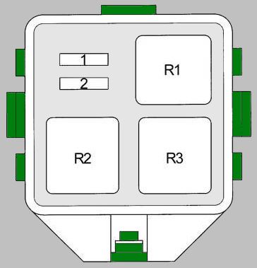
Auxiliary Relay Box #2
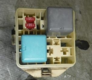
General overview.
| Diagram | |
|---|---|
|
|
| R1 | Headlight relay |
| R2 | Dimmer relay (DIM) |
| R3 | Unused |
| 1 | H-LP HI RH - Right headlight high beam, daytime running lights (DRL) 10A |
| 2 | H-LP HI LH - Left headlight high beam, instrument cluster, daytime running lights (DRL) 10A |
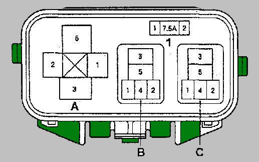
ABS Relay Box #4
Diagram layout.
|
|
| No. | Description |
| A | - Unused (models without VSC); - ABS MTR relay (models with VSC) |
| B | - ABS MTR relay (models without VSC); - ABS CUT relay (models with VSC) |
| C | - ABS SOL relay (models without VSC); - Unused (models with VSC) |
| 1 | - ABS fuse No. 3 (models without VSC); - Unused (models with VSC) |
Battery Fusible Link Block
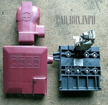
General overview.
| Diagram | ||
|---|---|---|
|
||
| No. | Circuit / Application | A |
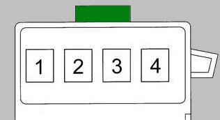
| 1 | MAIN - Fuses: “EFI”, “DOME”, “HORN”, “ST”, “AM2”, “H-LP LH”, “H-LP RH”, “H-LP LH (HI)”, “H-LP RH (HI)”, “H-LP LH (LO)”, “H-LP RH (LO)” | 60 |
| 2 | START/STOP system | 80 |
| 3 | ALT - Fuses: “ECU-B”, “TAIL”, “D/L”, “OBD”, “RDI”, “AM1”, “HAZ”, “HTR”, “HTR-SUB1”, “POWER”, “STOP”, “DEF”; Charging system | 100/120 |
| 4 | ABS braking system | 60 |
Passenger Compartment
General location of electrical control units (Left-Hand Drive / LHD models).
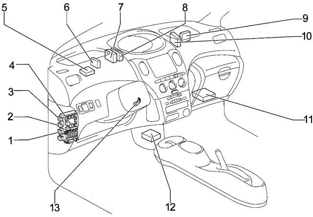
|
|
| No. | Control Module / Component |
| 1 | Front fog lamp relay |
| 2 | Rear window defogger relay |
| 3 | Tail lamp / side light relay |
| 4 | Instrument panel fuse box |
| 5 | Wireless door lock receiver |
| 6 | Headlight / lighting relay |
| 7 | Daytime running light (DRL) relay |
| 8 | Power door lock relay |
| 9 | A/C amplifier control unit |
| 10 | PTC heater amplifier |
| 11 | Engine and transmission control module (ECU/TCM) |
| 12 | SRS airbag sensor assembly / ECU |
| 13 | Transponder key amplifier |
Passenger Compartment Fuse Box
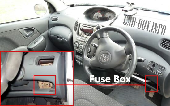
The fuse box is located behind a removable cover under the dashboard. On left-hand drive (LHD) models, the layout is mirrored.
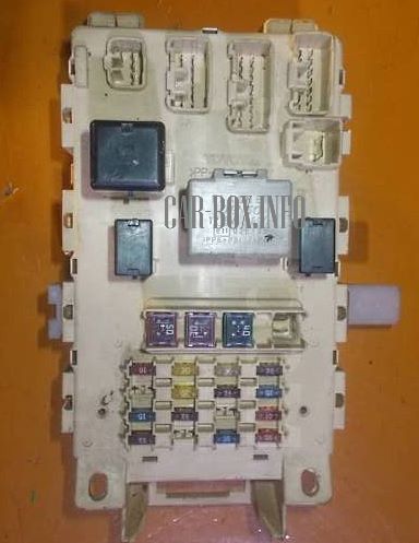
Photo example of the interior fuse box.
| Diagram | ||
|---|---|---|
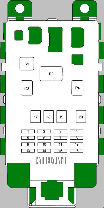
|
||
| No. | Circuit / Description | A |
| 1 | GAUGE - Instrument cluster, gauges, ABS, air conditioning, reverse lamps, charging system, central locking system, power door lock ECU, Engine Control Module, Transmission Control Module, DRL, warning chime, power sunroof, power windows, shift lock solenoid, turn signals, hazard lights, heater | 10 |
| 2 | Rear window defogger, heated side mirrors | 10 |
| 20 | ||
| 3 | Central locking system, power door lock ECU | 25 |
| 4 | Front fog lamps, headlights, headlight leveling module, warning chime, rear fog lamps, side marker / tail lamps | 7.5 |
| 5 | Unused | - |
| 6 | WIPER - Windshield/rear wiper and washer systems, power door locks | 20 |
| 7 | Headlights, rear fog lamps | 7.5 |
| 8 | Front fog lamps | 15 |
| 9 | CIG - Toyota FunCargo cigarette lighter fuse, digital clock, instrument cluster, warning chime, multi-information display, auxiliary power outlet, audio system, power side mirrors | 15 |
| 10 | ECU-B - ABS system, interior lamps, multi-information display, PTC auxiliary heater, cooling fan, SRS airbag system, climate control system | 7.5 |
| 11 | OBD - On-Board Diagnostics (OBD-II) port | 7.5 |
| 12 | TURN-HAZ - Turn signals, hazard warning flasher | 10 |
| 13 | A/C - Air conditioning system, heater controls | 7.5 |
| 14 | SEAT-HTR - Heated seats | 10 |
| 15 | Unused | - |
| 16 | STOP - Engine Control Module, Transmission Control Module, shift lock solenoid, brake lamps | 10 |
| 17 | AM1 - Ignition switch power supply: “ACC”, “GAUGE”, “DEF” (“DEF RLY”), “S-HTR”, “WIPER”, “ECU-IG” | 50 |
| 18 | POWER - Power windows, power sunroof | 30 |
| 19 | HTR - Air conditioning blower motor, heater system | 40 |
| 20 | DEF - Rear window defogger, heated side mirrors | 30 |
| R1 | Heater / blower motor relay | |
| R2 | Turn signal & hazard flasher relay | |
| R3 | Power main relay (power windows, sunroof) | |
| R4 | Fuel pump relay (Circuit Opening Relay / C-OPN) | |
