The third generation Land Cruiser Prado replaced the J90 series in 2002. The new model received the "120th" index. Like its predecessor, the "third" Prado was produced in bodies with five or three doors: cars, respectively, received the designation J120 or J125. Compared to the 90th series, the model has become noticeably more comfortable, more luxurious in equipment and slightly increased in size. Demonstrating the technological excellence of the novelty, the engineers presented new electronic start assistance systems on the ascent and during the descent.

Considered fuse diagrams for Toyota Land Cruiser Prado 120/125: 2002, 2003, 2004, 2005, 2006, 2007, 2008, 2009 year release.
In the engine compartment
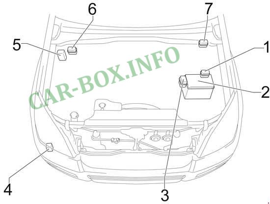
Location of components:
- Relay box # 1,
- Fuse box,
- Relay box # 2,
- Relay for headlamp wipers,
- Stability control unit (without VSC),
- Relay box # 3 (left hand drive),
- Relay box No. 3 (right hand drive)
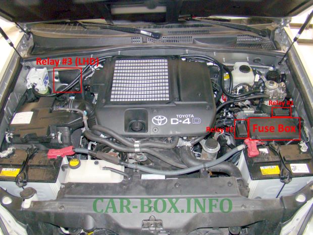
Photo location.
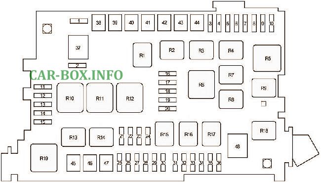
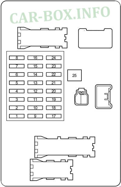
Fuse box
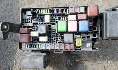
General view.
| Diagram | ||
|---|---|---|
|
||
| No. | Description | A |
| 1 | Spare | 10 |
| 2 | 15 | |
| 3 | Cooling fan | 20 |
| 4 | Rear air conditioner | 30 |
| 5 | Heated mirrors | 10 |
| 6 | Brake lights, auxiliary brake light, gear selector lock, ABS, VSC, A-TRC, height-adjustable rear suspension | 10 |
| 7 | Empty | - |
| 8 | Front fog lamps | 15 |
| 9 | Viscous heater | 7.5 |
| 10 | Diagnostic connector | 7.5 |
| 11 | Low beam right | 10 |
| 12 | Low beam left | 10 |
| 13 | High beam right | 10 |
| 14 | High beam left | 10 |
| 15 | Oxygen sensor, MAF sensor | 10 |
| 16 | Air conditioning | 7.5 |
| 17 | Heated rear window | 30 |
| 18 | Height-adjustable rear suspension | 10 |
| 19 | Fuel heating | 20 |
| 20 | Heated seats | 20 |
| 21 | Interior lighting, personal lighting, wireless remote control system, ignition switch lighting, door lighting | 10 |
| 22 | Radio cassette | 20 |
| 23 | ABS, VSC, A-TRC, air conditioning, refrigerator, windows | 10 |
| 24 | Body electrical control unit | 10 |
| 25 | Short pin | - |
| 26 | Charging system | 7.5 |
| 27 | Empty | - |
| 28 | Horn | 10 |
| 29 | Air fuel ratio sensor | 15 |
| 1KD − FTV: Fuel pump | 15 | |
| 30 | Direction indicators, hazard warning lights | 15 |
| 31 | Multiport fuel injection system / sequential multiport fuel injection system | 10 |
| 32 | Fuel pump control unit, petrol pump, multiport fuel injection system / sequential multiport fuel injection system | 20 |
| 1KD − FTV : Fuel pump control unit, fuel pump, multiport fuel injection system / sequential multiport fuel injection system | 25 | |
| 33 | Driver's window regulator | 20 |
| 34 | central locking | 25 |
| 35 | Empty | - |
| 36 | Audio system | 30 |
| 37 | without PTC : Heated rear window relay, ignition relay, fuses: "HEATER", "CDS FAN", "AM1", "J / B", "VISCUS", "OBD", "MIR HEATER", "STOP", " FR FOG "," AIRSUS "," RR A / C "and" STOP " | 120 |
| with PTC : Heated rear window relay, ignition relay, fuses: "HEATER", "CDS FAN", "AM1", "J / B", "VISCUS", "OBD", "MIR HEATER", "STOP", " FR FOG "," PTC-1 "," PTC-2 "," PTC-3 "," AIRSUS "," RR A / C "and" STOP " | 140 | |
| 38 | Air conditioning | 50 |
| 39 | Height-adjustable rear suspension | 50 |
| 40 | Fuses: "ACC", "CIG", "IG1", "IG1 NO.2", "ECU-IG", "FR WIP-WSH", "RR WIP", "RR WSH", "DIFF", "TEMS "and" STA " | 50 |
| 41 | Auxiliary heater | 40 |
| 42 | Fuses: "PWR OUTLET", "P FR P / W", "P RR P / W", "D RR P / W", "DP / SEAT", "PP / SEAT", "POWER", "TAIL" and "PANEL" | 50 |
| 43 | Auxiliary heater | 40 |
| 44 | 40 | |
| 45 | ABS, VSC, A-TRC | 40 |
| 46 | Starting system, fuses: "IGN", "GAUGE" and "SRS" | 30 |
| 47 | without stability control system: ABS | 30 |
| ABS (Anti-lock Braking System), VSC (Vehicle Stability Control), A-TRC (Active Traction Control) | 50 | |
| 48 | Glow plugs | 80 |
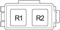
| Relay | ||
| R1 | Cooling fan | |
| R2 | Auxiliary relay (ACC CUT) | |
| R3 | Fog lamps | |
| R4 | Starter | |
| R5 | Ignition | |
| R6 | Heater | |
| R7 | A / C Compressor Clutch | |
| R8 | Empty | |
| R9 | Heated rear window | |
| R10 | Anti-lock brake system pump | |
| R11 | Active traction control | |
| R12 | Anti-lock braking system | |
| R13 | Downhill assist system | |
| R14 | Fuel pump (C / OPN) or EDU | |
| R15 | Empty | |
| R16 | (EFI) Engine control unit | |
| R17 | Air fuel ratio sensor | |
| R18 | Fuel pump relay | |
| R19 | Headlamp | |
Relay blocks
Diagram.
| No. | Name |
| Block #1 | |
|
|
| R1 | Starter |
| R2 | Glow plugs |
| Block #2 | |

|
|
| R1 | Air suspension |
| R2 | Dimmer (with daytime running lamps) |
| Block #3 | |
|
|
| R1 | Auxiliary heater (No. 1,2,3) |
| R2 | |
| R3 | |
In the pasenger compartment
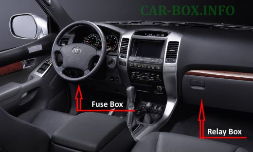
Location of components.
Fuse box
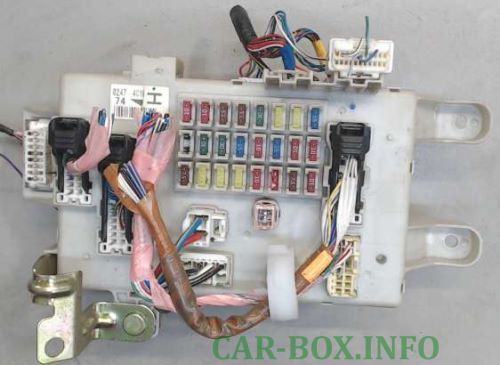
General view.
| Diagram | ||
|---|---|---|
|
||
| No. | Description | A |
| 1 | Fuel pump control unit, multiport fuel injection system / sequential multiport fuel injection system, ABS, VSC, A-TRC | 10 |
| 2 | SRS airbag system | 10 |
| 3 | Instrument cluster | 7.5 |
| 4 | Multiport fuel injection system / sequential multiport fuel injection system | 7.5 |
| 5 | Windscreen wiper and washer | 30 |
| 6 | Electronic adjustable suspension | 20 |
| 7 | Rear differential lock, center differential lock | 20 |
| 8 | Rear wiper | 15 |
| 9 | Empty | - |
| 10 | Left Hand Drive: Power Driver Seat | 30 |
| Right Hand Drive: Power Passenger Seat | 30 | |
| 11 | Left Hand Drive: Power Passenger Seat | 30 |
| Right Hand Drive: Power Driver Seat | 30 | |
| 12 | Power Outlet | 15 |
| 13 | Air conditioner, refrigerator | 10 |
| 14 | Rear window washer | 15 |
| 15 | Gear selector lock, power windows, ABS, VSC, A-TRC, air conditioning, sunroof, sockets | 10 |
| 16 | ABS, VSC, A-TRC, air conditioning, charging system, heated rear window, reversing lamps, direction indicators, alarm | 10 |
| 17 | Fuel pump control unit | 7.5 |
| 18 | Front passenger window regulator | 20 |
| 19 | Left hand drive: Rear right power window | 20 |
| Right hand drive: Rear right power window | 20 | |
| 20 | Left hand drive: Rear left power window | 20 |
| Right hand drive: Rear left power window | 20 | |
| 21 | Instrument panel illumination | 10 |
| 22 |
|
10 |
| 23 | Automatic transmission control unit, power outlets, power mirrors, audio system | 7.5 |
| 24 | cigarette lighter fuse | 10 |
| 25 | Power Windows, sunroof | 30 |
| Relay | ||
|
||
| R1 | Horn | |
| R2 | Parking lamps | |
| R3 | Power (windows, sunroof) | |
| R4 | Sockets (ACC SKT) | |
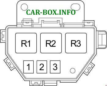
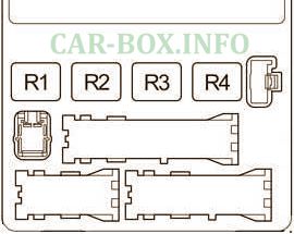
Relay box
Diagram.

|
|
| No. | Name |
| R1 | Panel |
| R2 | Reversing lamps |
| R3 | Heated mirrors |
