After the 2002 update, the exterior of the model was revised. The updated version is distinguished by a new front bumper and a radiator grill, updated taillights, and also changes were made to the electrics. In this article, we will take a detailed look at the fuse box diagrams for the the Toyota Land Cruiser 10th generation (body J100 / J105) restyled 2002, 2003, 2004, 2005, 2006, 2007 release.

Here you will find the locations and photos of distribution boxes. The fuses responsible for the “Cigarette lighter” and “Fuel Pump” are highlighted in bold.
In the engine compartment

The main block is located near the battery. Also on the positive terminal of the battery there is a board consisting of high-power fuse-links.
Main fuse box
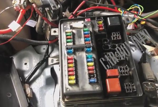
Access example.
| Assigment of fuses in the engine compartment | ||
|---|---|---|

|
||
| No. | Description | A |
| 1 | Empty | - |
| 2 | Empty | - |
| 3 | Empty | - |
| 4 | Empty | - |
| 5 | 2002-2005: sequential multiport fuel injection system | 7.5 |
| WIP−S — 2006-2007 | 7.5 | |
| 6 | Trailer lamps | 30 |
| 7 | Heated mirrors | 15 |
| 8 | Rear heater | 10 |
| 9 | Hazard warning lamps, turn signal / flasher | 15 |
| 10 | Charging system | 7.5 |
| 11 | NV − IR | 20 |
| 12 | Fog lamps | 15 |
| 13 | Trailer lamps (brake lamps) | 30 |
| 14 | Headlight cleaners | 20 |
| 15 | Charging system | 10 |
| 16 | Instrument panel illumination | 7.5 |
| 17 | Trailer lamps (side lamps) | 30 |
| 18 | Side lamps | 15 |
| 19 | Fuse: "ECU-B2" | 30 |
| 20 | Telephone | 7.5 |
| 21 | Audio system | 30 |
| 22 | EFI 1 - sequential multiport fuel injection system | 25 |
| ECD 1 - sequential multiport fuel injection system | 25 | |
| 23 | Fuse: "IGN" | 15 |
| 24 | Multiport fuel injection system / sequential multiport fuel injection system | 10 |
| 25 | Horn | 10 |
| 26 | Empty | - |
| 27 | Low beam right | 10 |
| 28 | Low beam left | 10 |
| 29 | High beam right | 20 |
| 30 | High beam left | 20 |
| 31 | ABS system | 40 |
| 32 | 50 | |
| 33 | AHC - Active body height control (AHC) | 50 |
| 34 | STARTER - Start system | 30 |
| 35 | PIN A - Fuses: "BAT", "AMP" | |
| 36 | PIN B - Fuses: "HAZ-TRN", "ALT-S" | |
| 37 | GLOW - Engine preheating system | 80 |
| Relay | ||
| R1 | Heater (HTR) | |
| R2 | ABS system (ABS MTR1 / 2) | |
| R3 | ||
| R4 | ABS SOL system | |
| R5 | Engine control unit (EFI / ECD) | |
| R6 | Active body height control (AHC) | |
| R7 | Fuel pump | |
| R8 | Fuel pump relay Toyota Land Cruiser 100 | |
| R9 | Starter | |
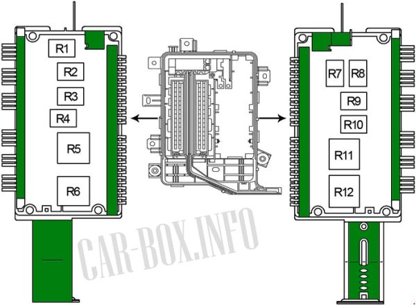
| Additional relay modules are located on the sides of the block | ||
|
||
| R1 | Relay switch for coolant temperature | |
| R2 | A / C Compressor Clutch (MG CLT) | |
| R3 | Cooling fan (CDS FAN) | |
| R4 | Horn | |
| R5 | Headlamps (HEAD) | |
| R6 | High Beam (HEAD HI) | |
| R7 | Heated mirrors (MIR HTR) | |
| R8 | Rear heater (RR HTR) | |
| R9 | Instrument panel illumination (PANEL) | |
| R10 | Front fog lamps (FR FOG) | |
| R11 | Ignition (IG1) | |
| R12 | Side lamps (TAIL) | |
Power fuse box
Located on the battery.
| Diagram | ||
|---|---|---|

|
||
| 1 | Air conditioner / heater | 50 |
| 2 | J / B1 - Relay "IG1 NO.1", relay "TAIL", fuses: "MIR HTR", "RR HTR", "TOWING BRK", "TOWING", "FR FOG" | 120 |
| 3 | J / B2 - Relay "IG1 NO.2", relay "ACC", fuses: "DEFOG", "AM1", "LH SEAT", "STOP", "ECU-B1", "SUN ROOF", "OBD- 2 "," DOOR " | 120 |
| 4 | J/B3 — Реле «IG1 NO.3», предохранители: «SECURITY», «TIL & TEL», «RH SEAT», «RR A/C», «P/W (RR)», «P/W (RL)», «P/W (FR)», «P/W (FL)» | 120 |
| 5 | MAIN - "HEAD HI" relay, "HEAD" relay, fuses: "ABS 1", "ABS 2", "PIN A", "EFI OR ECD NO.1", "PIN B", "AM2", "STARTER" "," HORN "," ECTS " | 120 |
| 6 | ALT - Fuses: "J / B1", "J / B2", "J / B3", "HTR" | 140 |
In the passenger compartment
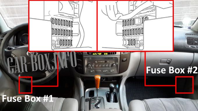
LHD Models: The main unit (# 1) is located on the driver's side, at the bottom of the dashboard. The add-on unit (# 2) is located on the passenger side.

Right-hand drive models.
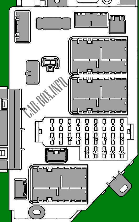
Fuse box #1
Diagram.
|
||
| No. | Description | A |
| 1 | 12V Power Outlet | 15 |
| 2 | Toyota Land Cruiser 100 cigarette lighter fuse | 15 |
| 3 | Instrument panel illumination | 7.5 |
| 4 | Multiport fuel injection system / sequential multiport fuel injection system | 7.5 |
| 5 | Heated rear window | 20 |
| 6 | Active body height control (AHC) | 15 |
| 7 | Fuel heating | 20 |
| 8 | Auxiliary heater | 7.5 |
| 9 | Active body height control (AHC) | 20 |
| 10 | Toxicity Reduction System (EFI / ECD) | 10 |
| 11 | Instrument cluster | 10 |
| 12 | sequential multiport fuel injection system | 10 |
| 13 | Navigation system | 10 |
| 14 | Double locking system | 15 |
| 15 | Trailer charging system | 30 |
| 16 | Air conditioning | 15 |
| 17 | Brake lamps | 15 |
| 18 | OBD2 diagnostic connector | 7.5 |
| 19 | Engine idle system | 7.5 |
| 20 | Power left seat | 30 |
| 21 | Central locking, power windows | 25 |
| 22 | Sunroof | 25 |
| 23 | Rear wiper | 15 |
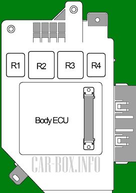
| Assignment of relay modules on the rear side of the unit | ||
|
||
| R1 | Heated rear window | |
| R2 | Ignition (IG1) | |
| R3 | Ignition (ACC) | |
| R4 | Interior lamps | |
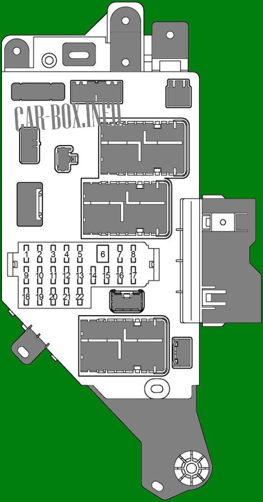
Fuse box #2

General view.
| Diagram | ||
|---|---|---|
|
||
| No. | Appointment | A |
| 1 | Central locking, power windows | 10 |
| 2 | All-wheel drive system | 20 |
| 3 | Windscreen washer | 15 |
| 4 | Audio system | 10 |
| 5 | Interior lamps | 10 |
| 6 | Variable Ratio Steering | 40 |
| 7 | Front left power window | 20 |
| 8 | Rear left power window | 20 |
| 9 | Wiper | 25 |
| 10 | Rear air conditioner | 10 |
| 11 | Heated seats | 15 |
| 12 | Reversing lamps | 10 |
| 13 | Instrument cluster | 7.5 |
| 14 | sequential multiport fuel injection system | 7.5 |
| 15 | Anti-theft system | 7.5 |
| 16 | Rear right power window | 20 |
| 17 | Front right power window | 20 |
| 18 | Trailer charging system | 30 |
| 19 | Empy | - |
| 20 | Steering column tilt and height adjustment system | 20 |
| 21 | Rear air conditioner | 30 |
| 22 | Right power seat | 30 |
| Relay on the back of the unit | ||

|
||
| R1 | Brake lamps | |
| R2 | Empty | |
| R3 | Ignition (IG1 # 3) | |
| R4 | Ignition cut (ACC CUT) | |
