5 years after the launch of Toyota Ractis in Japan, the second generation of this compact van was released. The novelty fully retained the practicality of the previous generation and acquired a more stylish appearance. This time the company has released a left-hand drive analogue - in Europe it is called Verso-S. In this article, we will take a detailed look at the fuse box diagrams for the Toyota Ractis 2 (Verso-S) 2nd generation (P120) 2010, 2011, 2012, 2013, 2014, 2015, 2016, 2017, 2018 release.

Here you will find the locations and photos of distribution boxes. The fuses responsible for the “Cigarette lighter” and “Fuel Pump” are highlighted in bold.
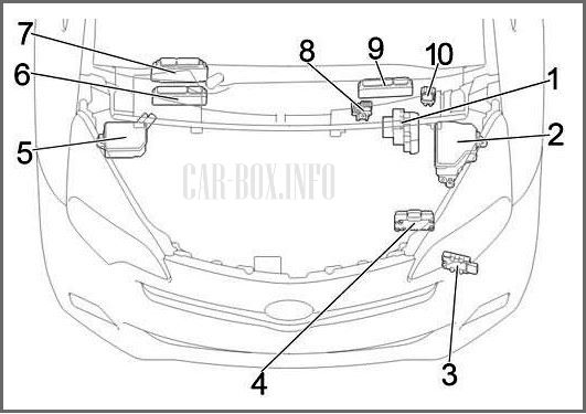
In the engine compartment
General layout of electrical equipment.
|
|
| 1 | Driven skid control ECU |
| 2 | Main fuse box |
| 3 | Fuel pump control module |
| 4 | ECO Run |
| 5 | Additional fuse box |
| 6 | Left hand drive with 1NR-FE engine: ECM |
| 7 | Left hand drive with 1ND-TV engine: ECM |
| 8 | Fusible links on battery |
| 9 | Right hand drive: ECM system |
| 10 | Glow plug relay |
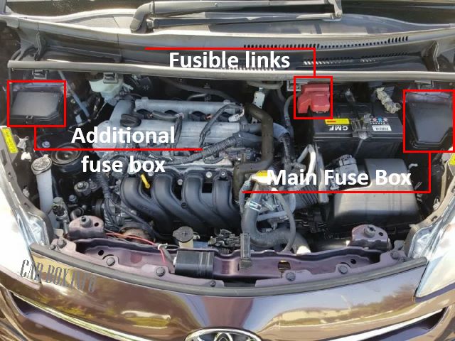
There are three distribution boxes here: the main one on the left side near the battery, an additional one on the right side of the engine compartment, and there is also a high-power fuse-link board on the battery . To access the fuses, it is necessary to squeeze the latches to remove the protective covers of the blocks.
Main fuse box
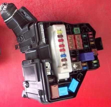
Photo - an example of the execution.
| Diagram | ||
|---|---|---|
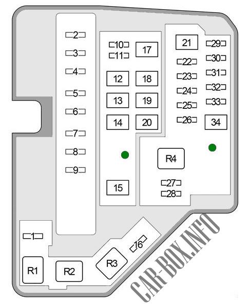
|
||
| No. | Description | A |
| 1 | ID / UP - sequential multiport fuel injection system | 7.5 |
| 2 | EFI MAIN - Petrol: sequential multiport fuel injection system | 20 |
| ECD MAIN - Diesel: sequential multiport fuel injection system, "EFI 2" fuse | 30 | |
| 3 | EFI 3 - sequential multiport fuel injection system | 7.5 |
| 4 | Horn | 10 |
| 5 | EFI 2 - Stop-start system, sequential multiport fuel injection system | 10 |
| 6 | Intelligent entry and start system, sequential multiport fuel injection system, multi-mode manual transmission, SRS airbag system, steering lock system, brake lights, stop and start system | |
| 7 | IG2 - sequential multiport fuel injection system | 10 |
| 8 | MET - Sensor and counters, Stop & Start system | 7.5 |
| 9 | Empty | - |
| 10 | Empty | - |
| 11 | PWR HTR - Electric heater, sequential multiport fuel injection system | 25 |
| 12 | EPS - Electric power steering | 50 |
| 13 | ABS 2 - ABS systems, VSC | 30 |
| 14 | DEF - Heated rear window | 30 |
| 15 | PTC heater, outside rearview mirror heaters | 80 |
| 16 | Empty | - |
| 17 | Air conditioning | 40 |
| 18 | Empty | - |
| 19 | RDI FAN - Electric cooling fan | 30 |
| 20 | Anti-lock braking system ABS, VSC | 50 |
| 21 | Stop and start system | 40 |
| 22 | ST - Start system | 30 |
| 23 | Empty | - |
| 24 | D / L - Power door lock | 25 |
| 25 | DCC - Fuses "DOME", "ECU-B NO.1" | 30 |
| 26 | STR LOCK - Steering lock system | 20 |
| 27 | ECU-B 1 - Main body ECU, intelligent entry and start system | 5 |
| 28 | DOME - Interior lighting, audio system, VSC | 15 |
| 29 | ETCS - sequential multiport fuel injection system | 10 |
| 30 | HAZ - Turn Signal Lamps (flasher) | 10 |
| 31 | AM2 - sequential multiport fuel injection system, intelligent entry and start system, multi-mode manual transmission | 7.5 |
| 32 | ECU-B 2 - Gauge & Meters, Power Door Lock, Wireless Remote Control, Stop & Start System, Smart Entry and Start System, Multi-Mode Manual Transmission, Air Conditioning System | 5 |
| 33 | Empty | - |
| 34 | R / I - Fuses "EFI MAIN", "ECD MAIN", "EFI NO.2", "EFI NO.3", "IG2", "IGN", "MET", "HORN" | 50 |
| R1 | Cooling fan relay (FAN) | |
| R2 | ||
| R3 | Heated rear window (DEF) | |
| R4 | Start system (ST) with stop system; 1NZ-FE: Starting system (ST2) | |
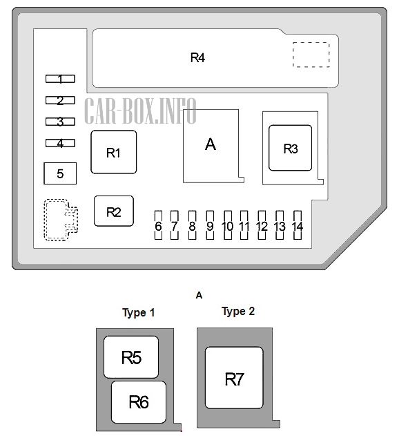
Additional fuse box
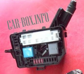
General view.
| Diagram | ||
|---|---|---|
|
||
| No. | Decoding | A |
| 1 | Empty | - |
| 2 | EU-DRL - Headlamps | 15 |
| 3 | S-HORN - sequential multiport fuel injection system, horn | 10 |
| 4 | H-LP MAIN - Fuses "H-LP RH LO", "H-LP LH LO" | 7.5 |
| 5 | MMT - Multi-Mode Manual Transmission | 50 |
| ST - with a stop and start system; 1NZ-FE: Starting system | 40 | |
| 6 | Right Headlamps (high beam) - H-LP RH HI | 10 |
| 7 | Left Headlamps (high beam), sensor and instruments - H-LP LH HI | 10 |
| 8 | Halogen: Right Headlamps (low beam) - H-LP RH LO | 10 |
| HID: right headlight (low beam) - H-LP RH LO | 15 | |
| 9 | Halogen: LH headlamps (low beam), manual headlamps range adjustment - H-LP LH LO | 10 |
| HID: left headlamps (low beam), manual headlamps range control - H-LP LH LO | 15 | |
| 10 | Empty | - |
| 11 | Empty | - |
| 12 | Empty | - |
| 13 | Empty | - |
| 14 | Empty | - |
| R1 | Dimmer (DIM) | |
| R2 | EU-DRL / S-HORN - Daytime running lights / Anti-theft device | |
| R3 | H-LP / US-DRL - Headlights / Daytime Running Lights | |
| R4 | Integration relay | |
| R5 |
|
|
| R6 | 1NR-FE, 1ND-TV: (O / P MTR) | |
| R7 | Multi-mode manual transmission | |
Battery fusible-links
Diagram.

|
||
| 1 | GLOW DC / DC - sequential multiport fuel injection system | 80 |
| 2 | MAIN - Fuses: BBC, S-HORN, ST, D / L NO.2, DCC, STR LOCK, ETCS, HAZ, AM2, ECU- B NO.2 "," R / I "," H-LP MAIN "," H-LP RH HI "," H-LP LH HI "," H-LP RH LO "," H-LP LH LO " , "MMT" | 80 |
| 3 | ALT - Charging system, Fuses: "PWR HTR", "EPS", "ABS NO.2", "DEF", "PTC", "HTR", "RDI FAN", "ABS NO.1", "TAIL NO .2 "," PANEL "," DOOR R / R "," DOOR P "," ECU-IG NO.1 "," ECU-IG NO.2 "," A / C "," GAUGE "," WASHER "," WIPER "," WIPER RR "," P / W "," DOOR R / L "," DOOR "," CIG "," ACC "," D / L "," OBD "," FOG RR " , "STOP", "AM1", "FOG FR", "DD / L", "SHADE", "S-HTR" | 120 |
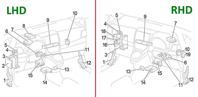
In the passenger compartment
General layout of electrical equipment.
|
|
| 1 | Connection module |
| 2 | Left hand drive: ECU for engine stop and start, ECU for power control |
| 3 | Fuse Box / Main Body ECU |
| 4 | Heater relay (HTR) |
| 5 | Relay board |
| 6 | Steering lock actuator |
| 7 | Power steering ECU |
| 8 | Transmission control ECU |
| 9 | Expansion module |
| 10 | Wiper relay |
| 11 | Transponder Key Amplifier |
| 12 | Connection module |
| 13 | ECU for gearshift lock |
| 14 | Central airbag sensor |
| 15 | Air conditioner amplifier |
| 16 | Right hand drive: ECU for engine stop and start |
| 17 | Right hand drive: Power control ECU |
| 18 | Right hand drive: Headlight range control ECU |
| 19 | Right hand drive: Double door lock control relay |
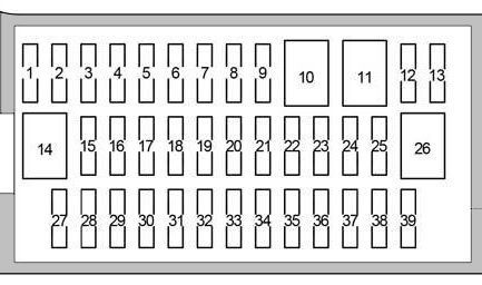
Fuse box
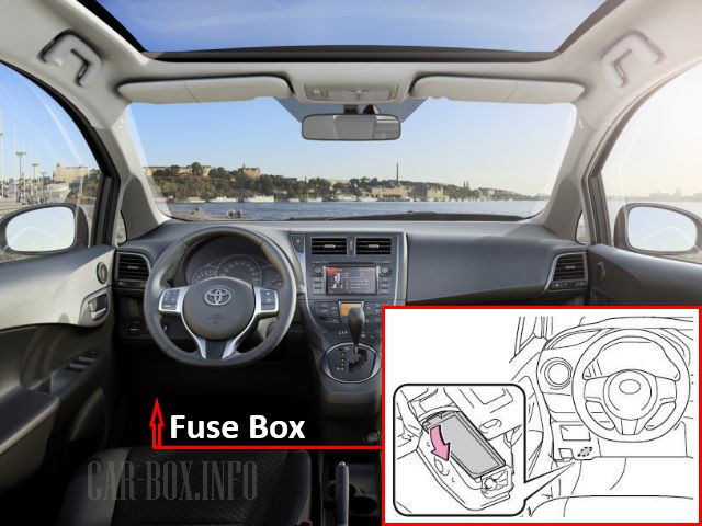
LHD models: Located on the driver's side, at the bottom of the dashboard. Above it is the relay board.

Right-hand drive models: Located on the passenger side, under the glove compartment. A relay board is located next to it.
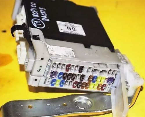
The photo shows an example.
| Diagram | ||
|---|---|---|
|
||
| No. | Description | A |
| 1 | Not used | - |
| 2 | Not used | - |
| 3 | Not used | - |
| 4 | Heated seats S-HTR | 15 |
| 5 | Not used | - |
| 6 | Not used | - |
| 7 | Power Mirrors - ECU-B 3 | 7.5 |
| 8 | Panoramic roof - SHADE | |
| 9 | Not used | - |
| 10 | Not used | - |
| 11 | Not used | |
| 12 | DD / L - Double door lock | 25 |
| 13 | Not used | - |
| 14 | Not used | - |
| 15 | FOG FR - up to June 2013: Front fog light | 15 |
| FOG FR - from June 2013 (TMC): Front fog light (TMC - Toyota Motor Corporation) | 15 | |
| FOG FR - from June 2013 (TMMF): Front fog light (TMMF - Toyota Motor Manufacturing France) | 7.5 | |
| 16 | Start system AM1 | 7.5 |
| 17 | STOP - sequential multiport fuel injection system, VSC, brake light, additional brake light | 7.5 |
| 18 | Rear fog lamps (FOG RR) | 7.5 |
| 19 | Not used | - |
| 20 | OBD diagnostic connector | 7.5 |
| 21 | D / L - Central locking, body ECM | 25 |
| 22 | ACC - Body ECU, Power Mirrors, Audio System, Gear Selector Lock | 5 |
| 23 | CIG - Fuse for Toyota Ractis 2 / Verso-S cigarette lighter, 12V sockets | 15 |
| 24 | Power Window - DOOR | 20 |
| 25 | Power Windows - DOOR R / L | 20 |
| 26 | Power Windows | 30 |
| 27 | Rear wiper | 15 |
| 28 | Wiper | 20 |
| 29 | WindScreen washer | 15 |
| 30 | Not used | - |
| 31 | Not used | - |
| 32 | GAUGE - Reversing lamps, gear selector lock, audio system, charging system, multiport fuel injection system / sequential multiport fuel injection system | 10 |
| 33 | A / C - Air conditioning, heated rear window, heated mirrors | 7.5 |
| 34 | ECU-IG 2 - VSC system | 5 |
| 35 | ECU-IG 1 - Cooling Fan, Heated Rear Window, VSC, Electric Power Steering, Body ECM, Wireless Control System, Tire Pressure Monitoring System | 5 |
| 36 | Window regulators (DOOR P) | 20 |
| 37 | Window lifters (DOOR R / R) | 20 |
| 38 | PANEL - Instrument Cluster, Instrument Panel lamps, Light Switch | 5 |
| 39 | TAIL NO.2 - Side lamps, license plate lamp | 10 |
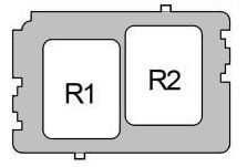
| Additional relay board | ||
|
||
| R1 | DOME CUT - Interior lamps | |
| R2 | FR FOG - Front fog lamps | |
Car body

Component locations:
- Door control receiver,
- Sunroof unit
- Tire pressure warning ECU and receiver
