The appearance of the model was preceded by a striking concept RAV Four (1989) in the form of a "beach" SUV. The abbreviation RAV stands for Recreation Active Vehicle. At the same time, Toyota abandoned the frame in favor of a monocoque body, and both suspensions were independent. The production RAV4 debuted in May 1994, first in Japan, then in other markets. The car is a typical representative of the SUV (Sport Utility Vehicle) class, combining the advantages of a passenger station wagon and a compact SUV. It was offered in three- or five-door versions.
In this material, we will consider the fuse circuits for the Toyota Rav 4 1st generation (XA10 body) 1994, 1995, 1996, 1997, 1998, 1999, 2000 model year.
In the engine compartment

Component locations:
- Main fuse box,
- Relay box,
- ABS module,
- High power fuses
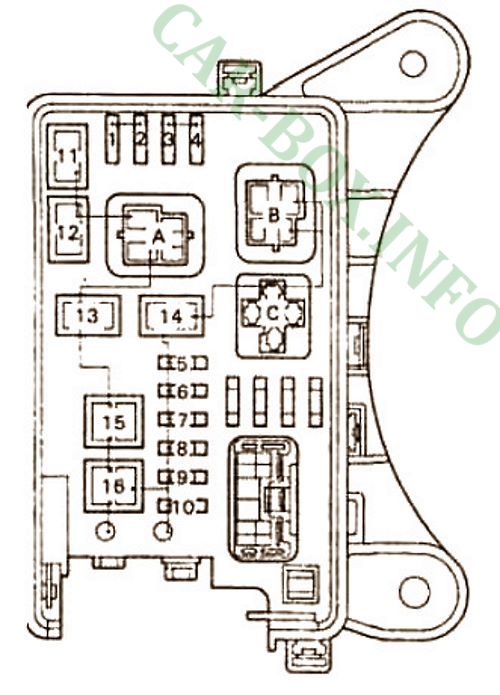
Main fuse box

General view of the main unit.
| Diagram | ||
|---|---|---|
|
||
| No. | Description | A |
| 1 | Left headlamp - low beam | 10 |
| 2 | Right headlamp - low beam | 10 |
| 3 | Left headlamp - high beam | 10 |
| Left headlamp | 15 | |
| 4 | Right headlamp - high beam | 10 |
| Right headlamp | 15 | |
| 5 | Generator "ALT-S" | 5 |
| 6 | Passenger compartment "DOME" | 10 |
| 7 | Emergency signaling "HAZ-HORN" | 15 |
| 8 | Injection system "EFI" | 15 |
| 9 | Radio | 15 |
| 10 | "AM2" - charging system | 20 |
| 11 | Electric cooling fan | 30 |
| 12 | 30 | |
| 13 | (LHD) - Headlight cleaner | 40 |
| 13 | (right-hand drive) - heater fan | 40 |
| 14 | starting system, headlight fuses | 30 |
| 15 | system ABS | 60 |
| 16 | Alternator "ALT" (right-hand drive) | 100 |
| Relay | ||
| A | Main | |
| B | Headlight relay | |
| C | Starter relay | |
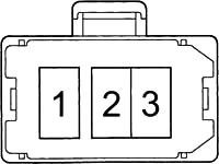
High Power Fuse Links
#4 on the picture.
| Diagram | ||
|---|---|---|
|
||
| No. | Appointment | A |
| 1 | Fuses "AM 2", "HAZ-HORN", "EFI", "DOME", "RADIO" and "ALT-S" | 80 |
| 2 | Rear lights, fuses "ABS", "RADIO", "HTR", "AM 1", "POWER", "STOP" and "DEF" | 100 |
| 3 | air conditioner and heater (fuse A / C) | 50 |
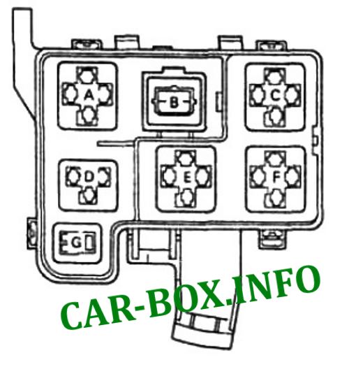
Relay box
#2 on the picture.
| Diagram | |
|---|---|
|
|
| No. | Description |
| A | Main relay of the injection system |
| B | Headlamp switching relay |
| C | A / C compressor electromagnetic clutch relay |
| D | Electric fan relay |
| E | |
| F | |
| G | Horn relay |
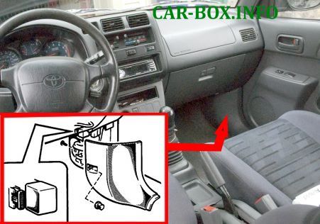
In the passenger compartment
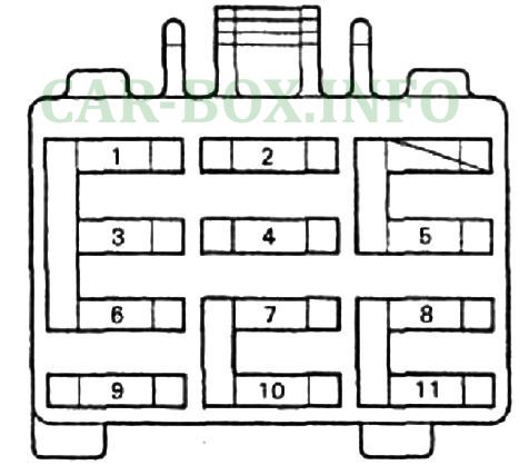
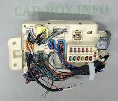
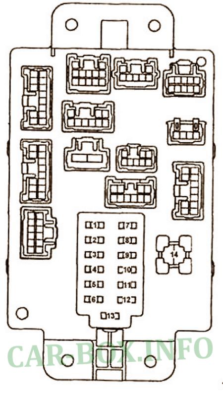
Main fuse box
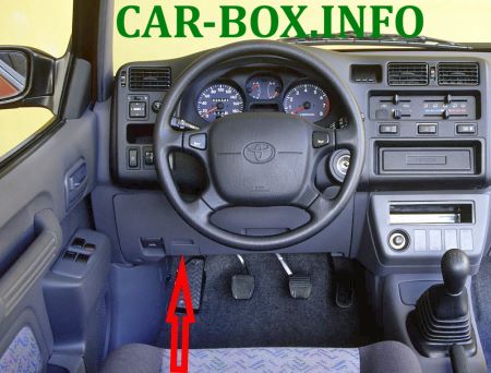
Located at the bottom of the dashboard on the driver's side, behind the protective cover.

Photo is an example.
| Diagram | ||
|---|---|---|
|
||
| No. | Description | A |
| 1 | Direction indicators | 7.5 |
| 2 | Heated rear window | 7.5 |
| 3 | Devices | 10 |
| 4 | Ignition | 7.5 |
| 5 | Stop lamps | 7.5 |
| 6 | Seat heater (LHD models) | 10 |
| 7 | Electronic control unit | 7.5 |
| 8 | Tail lamps | 7.5 |
| 9 | Cigarette lighter fuse and radio | 15 |
| 10 | Wiper | 20 |
| 11 | Panel | 10 |
Additional fuse box
Located next to the main one.
Diagram (type 1)
|
||
|
||
| 1 | power take-off for connecting external devices | 15 |
| 2 | cigarette lighter fuse, audio system, electric drive for adjustment of external mirrors | 15 |
| 3 | SRS system | 10 |
| 4 | wipers and washers, headlamp washer | 20 |
| 5 | automatic transmission control unit, injection system | 10 |
| 6 | instruments and indicators, direction indicators, daytime lighting system | 10 |
| 7 | brake lamps | 10 |
| 8 | tail lamps, reversing lamps, headlamps range control | 15 |
| 9 | outside mirror heaters | 10 |
| 10 | SRS indicator | 10 |
| 11 | sound signal (horn) | 10 |
| 12 | rear door window heater | 20 |
| 13 | (for PWR OUTLET, SRS-ACC, CIG, WIPER, ECU-IG, TURN & GAUGE fuses) | 10 |
| 14 | central locking, electric sunroof, electric power windows | 30 |
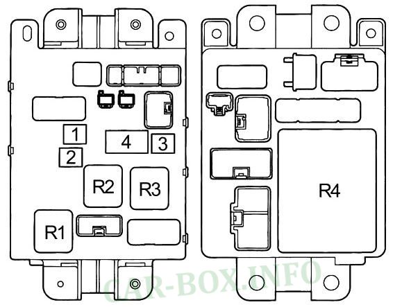
| Digram (type 2) | ||
|
||
|
||
| R1 | Heater | - |
| R2 | Main power relay | - |
| R3 | Back lamps | - |
| R4 | Integration relay | - |
| 1 | Power windows, power door locking system | 30 |
| 2 | Heated rear window | 30 |
| 3 | Fuses "CIG & RAD", "WIPER", "GAUGE", "ECU-IG", "TURN", "TAIL" and "PANEL" | 40 |
| 4 | Interference filter | |
Relay box #1

Also on the driver's side there is an additional block with relay modules.

|
|
| R1 | Open circuit relay |
| R2 | Empty |
| R3 | Rear fog lamps (Europe models) |
| R4 | Turn indicator |
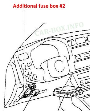
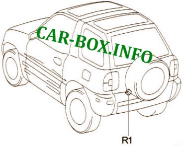
Relay box #2
Another block is located on the passenger side.

Diagram and purpose of the elements:
- R1 - Heater relay;
- 1 - Air conditioning system
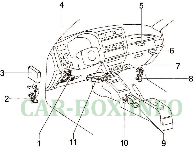
General layout
General layout of electrical equipment in the cabin.
|
|
| No. | Component |
| 1 | Main fuse box |
| 2 | Relay box |
| 3 | ABS ECU |
| 4 | Additional fuse box #2 |
| 5 | Air conditioner amplifier |
| 6 | Door lock control relay |
| 7 | Cruise control ECU |
| 8 | Passenger side unit |
| 9 | Airbag sensor module |
| 10 | ECU for gearshift lock |
| 11 | Engine control module |
The rear wiper relay is located in the luggage compartment.
