Most of the electrical circuits in the Japanese crossover are protected by fuses. Powerful current consumers are connected via relays. Most of the protective elements are located in distribution boxes in the passenger compartment and under the hood.

Information on the diagrams is suitable for the 2nd generation Toyota RAV4 models (bodies CA20 / XA20) 2000, 2001, 2002, 2003, 2004, 2005, 2006 with 1AZ-FSE engines (2.0 l D-4), 1ZZ- FE (1.8 L).
In the engine compartment
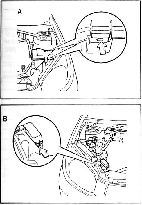
Block "A" is on the driver's side, block "B" on the passenger side. Both are covered with plastic covers.
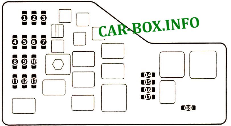
Block "A"
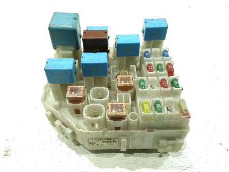
General view.
| Diagram | ||
|---|---|---|
|
||
| No. | Decoding | A |
| 1 | ALT-S charging system | 5 |
| 2 | Mass Air Flow Sensor A / F * 2 | 20 |
| C / OPN * 1 | ||
| 3 | Fuel injection system, "EFI2" and "EFI3" fuse circuit | 20 |
| 4 | Fuse circuit "RADIO" and "DOME" | 30 |
| 5 | Siren | 10 |
| 6 | Fuel injection system EFI2 | 5 |
| 7 | ABS system | 30 |
| 8 | Clock, spot light, air conditioning system, ignition switch light, fog lamps, instrument cluster, remote lock | 10 |
| 9 | Fuse circuit "H-LP RH" and "H-LP LH" | 30 |
| 10 | Fuel injection system, emission control system | 10 |
| 11 | Audio system | 15 |
| 12 | Air conditioning system | 5 |
| 13 | Starting system, IGN fuel injection system | 15 |
| 14 | ETCS system * 1 | 15 |
| 15 | Left headlamp | 10 |
| 16 | Right headlamp | 10 |
| 17 | IGN engine management system * 1 | 10 |
| 18 | ST start system | 5 |
| Note : * 1 - models with 1AZ-FSE engine, * 2 - models with 1ZZ-FE engines | ||
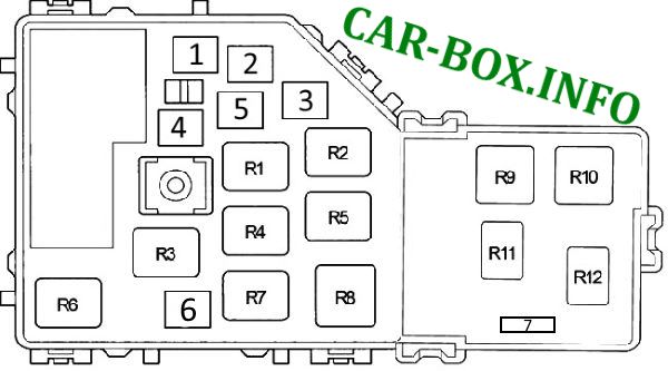
| Relay and additional fuses in block A | |
|
|
| No. | Appointment |
| R1 | Engine control unit (EFI MAIN) |
| R2 | Cooling fan (FAN NO.3) |
| R3 | Ignition (IG2) |
| R4 | Cooling fan (FAN NO.2) |
| R5 | Air Fuel Ratio (A / F) Sensor |
| R6 | Cooling fan (FAN NO.2) |
| R7 | Fuel pump (C / OPN) |
| R8 | Heater (HTR) |
| R9 | Starter (ST) |
| R10 | Daytime running lights (DRL) |
| R11 | Engine contol module |
| R12 | Empty |
| 1 | Battery discharge indicator, multiport fuel injection system / sequential multiport fuel injection system, starting system, airbags, fuse: IG2 30A |
| 2 | Air conditioner / heater 40A |
| 3 |
|
| 4 | Cooling fan 30A |
| 5 | ABS system 40A / 50A |
| 6 | Cooling fan 30A |
| 7 | Launch system |
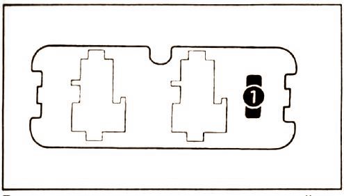
Block "B"
Diagram.
|
||
| No. | Appointment | A |
| 1 | ABS system | 7.5 |
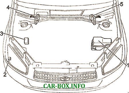
General arrangement
General arrangement of electrical modules in the engine compartment.
|
|
| 1 | Main fuse and relay box |
| 2 | Headlight wiper relay |
| 3 | Block B (ABS control) |
| 4 | Left Hand Drive : High Power Fuse Board |
| 5 | Right Hand Drive : High Power Fuse Board |
In the passenger compartment
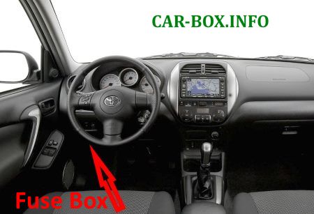
Located on the driver's side, at the bottom of the dashboard.

To access, you need to flip the protective cover.
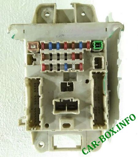
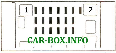
General view of the distribution box.
| Diagram | ||
|---|---|---|

|
||
| No. | Description | A |
| 1 | Brake lights, ABS system, automatic transmission control system, fuel injection system | 10 |
| 2 | Cigarette lighter fuse ra4 | 15 |
| 3 | Sockets for connecting additional devices | 15 |
| 4 | Seat heaters | 10 |
| 5 | Instrument Cluster Gauges and Indicators, Fog Lights and Lights, Seat Heaters, Instrument Cluster Lights, Air Conditioning | 7.5 |
| 6 | Fog lamps | 15 |
| 7 | Sound signal (horn) | 10 |
| 8 | Tail lamps, license plate illumination, instrument cluster illumination, headlamp position correction system | 7.5 |
| 9 | Fuse circuit "TAIL" and "PANEL" | 15 |
| 10 | Audio system, clock, electric mirrors, automatic transmission control system | 7.5 |
| 11 | Rear door glass heater | 20 |
| 12 | GAUGE: Reversing light, electric fans of the cooling and air conditioning system, automatic transmission indicators, charging system | 10 |
| 13 | OBD diagnostic system | 7.5 |
| 14 | IGN2: Battery Charge Indicator, SRS | 10 |
| 15 | Central locking, double locking system | 20 |
| 16 | Defroster for side mirrors | 10 |
| 17 | Rear door glass cleaner and washer | 15 |
| 18 | Windshield wiper and washer | 25 |
| 19 | ECU-IG: Hazard warning lights, gauges and indicators in instrument cluster, ABS system, headlight washer system, SRS system, automatic transmission control system | 10 |
|
||
| 1 | Sunroof, windows | 30 |
| 2 | Sockets, heated rear window, fuses: "ACC", "CIG", "ECU IG", "GAUGE", "RR WIP", "S − HTR" and "WIP" | 40 |
| Relay modules on the back of the unit | |
|---|---|
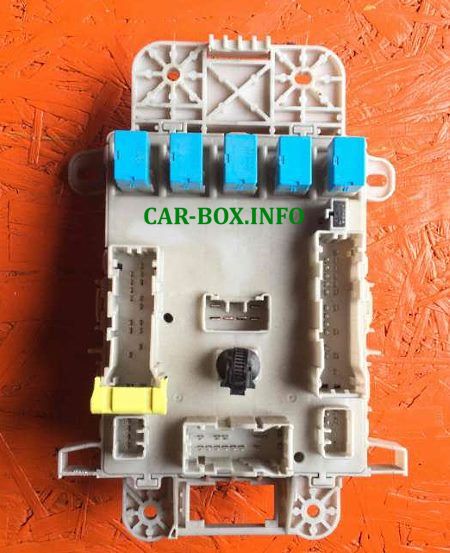
The photo shows an example. |
|

Diagram. |
|
| No. | Description |
| R1 | Horn |
| R2 | Rear fog lamps (RR FOG) |
| R3 | Heated rear window (DEF) |
| R4 | Sockets (PWR OUTLET) |
| R5 | Power windows, sunroof (PWR) |
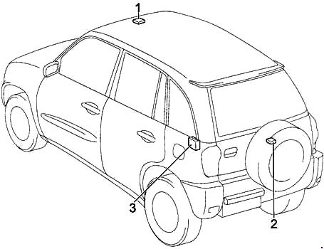
General arrangement
General arrangement of the electrical equipment of the passenger compartment.

|
|
| 1 | Fuse box |
| 2 | Left hand drive: Side light relay |
| 3 | Key transponder amplifier |
| 4 | Air conditioner amplifier |
| 5 | Engine and transmission control unit (automatic transmission) |
| 6 | Engine control unit (manual transmission) |
| 7 | Distribution block |
| 8 | |
| 9 | Central airbag unit |
| 10 | Selector lever lock control unit |
| 11 | Turn signal relay (alarm) |
|
|
| 1 | Relay and sunroof control unit |
| 2 | Rear wiper relay |
| 3 | Central locking receiver |
