
Table of Contents
Most electrical power circuits in this vehicle are protected by fuses, while high-current components are connected via relays. These protective components are housed in power distribution boxes located in both the engine compartment and the passenger compartment.
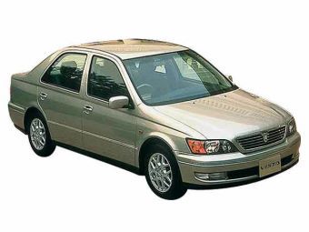
This information applies to 1998–2003 Toyota Vista (chassis codes SV50, SV55, AZV50, AZV55, ZZV50; MC platform) 2WD & 4WD models equipped with 1ZZ-FE (1.8 L), 3S-FE (2.0 L), and 3S-FSE (2.0 L D-4) engines.
Passenger Compartment Fuse Box
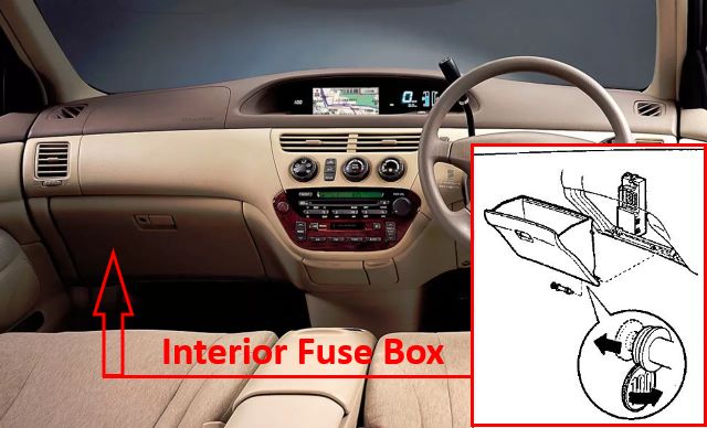
Located behind the glove box.
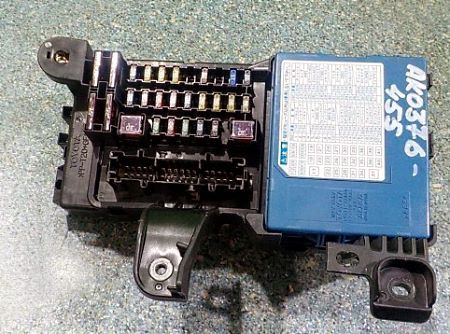
Representative example shown.
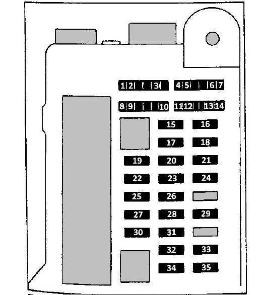
Models Produced Up to 04/2000
Fuse diagram.
|
||
| No. | A | Protected Circuit |
| 1 | 5 | Front fog lights |
| 2 | 5 | Parking lights |
| 3 | 5 | Electronic transmission control unit, hazard lights |
| 4 | 5 | Instrument cluster |
| 5 | 5 | Anti-lock braking system (ABS) |
| 6 | 5 | Turn signal indicators |
| 7 | 5 | Blower motor |
| 8 | 5 | Multi-information display |
| 9 | 5 | Heater system, keyless entry module |
| 10 | 5 | Interior lights |
| 11 | 5 | Multi-information display |
| 12 | 5 | Power windows |
| 13 | 5 | Rear window defogger |
| 14 | 5 | Reverse lights |
| 15 | 15 | Windshield washer |
| 16 | 15 | Brake lights |
| 17 | 7.5 | Turn signal lights |
| 18 | 20 | Windshield wiper de-icer |
| 19 | 30 | Sunroof |
| 20 | 10 | Air conditioning and heater controls |
| 21 | 20 | Ignition switch (AM1) |
| 22 | 10 | SRS airbag system |
| 23 | 7.5 | Shift lock system, clock, power side mirrors |
| 24 | 20 | Driver door power window |
| 25 | 30 | Central door locking |
| 26 | 15 | Rear window wiper |
| 27 | 15 | Cigarette lighter |
| 28 | 20 | Rear right power window |
| 29 | 7.5 | OBD-II diagnostic port |
| 30 | 7.5 | Windshield wiper de-icer |
| 31 | 20 | Front passenger power window |
| 32 | 20 | Rear left power window |
| 33 | 15 | Audio system |
| 34 | 25 | Wiper and washer control switch |
| 35 | 15 | Front fog lights |
Models Produced From 04/2000 Onward
Fuse diagram.
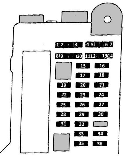
|
||
| No. | A | Protected Circuit |
| 1 | 10 | Front fog lights |
| 2 | 10 | Parking lights |
| 3 | 10 | Electronic transmission control unit, hazard lights |
| 4 | 7.5 | Instrument cluster |
| 5 | 7.5 | Anti-lock braking system (ABS) |
| 6 | 7.5 | Turn signal indicators |
| 7 | 7.5 | Blower motor |
| 8 | 7.5 | Multi-information display |
| 9 | 7.5 | Heater system, keyless entry module |
| 10 | 7.5 | Interior lights |
| 11 | 7.5 | Multi-information display |
| 12 | 7.5 | Power windows |
| 13 | 7.5 | Rear window defogger |
| 14 | 7.5 | Reverse lights |
| 15 | 15 | Windshield washer |
| 16 | 15 | Brake lights |
| 17 | 7.5 | Turn signal lights |
| 18 | 20 | Windshield wiper de-icer |
| 19 | 30 | Sunroof |
| 20 | 10 | Air conditioning and heater controls |
| 21 | 20 | Ignition switch (AM1) |
| 22 | 10 | SRS airbag system |
| 23 | 7.5 | Shift lock system, clock, power side mirrors |
| 24 | 20 | Driver door power window |
| 25 | 25 | Central door locking |
| 26 | 15 | Rear window wiper |
| 27 | 10 | Heated side mirrors |
| 28 | 15 | Cigarette lighter |
| 29 | 20 | Rear right power window |
| 30 | 7.5 | OBD-II diagnostic port |
| 31 | 7.5 | Windshield wiper de-icer |
| 32 | 20 | Front passenger power window |
| 33 | 20 | Rear left power window |
| 34 | 15 | Audio system / Radio cassette player |
| 35 | 25 | Wiper and washer control switch |
| 36 | 15 | Front fog lights |
Engine Compartment Fuse Box
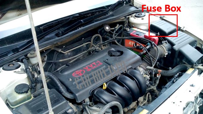
The fuse box is located on the right side of the engine compartment.
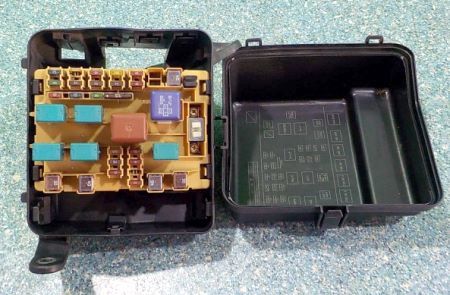
Overview of the power distribution box.
Models Produced Up to 04/2000
Fuse diagram.
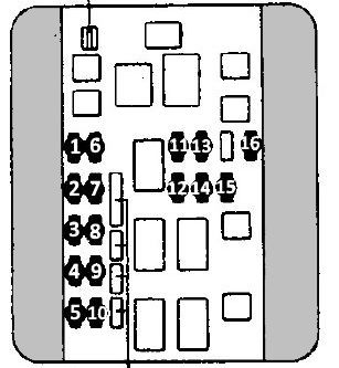
|
||
| No. | A | Protected Circuit |
| 1 | 10 | Security siren |
| 2 | 20 | EFI engine ECU |
| 3 | 10 | Ignition switch (AM2) |
| 4 | 15 *2 |
Electronic Throttle Control System (ETCS) |
| 5 | 15 | Engine ECU (IG2 circuit) |
| 6 | 10 | Horn |
| 7 | 7.5 | Alternator |
| 8 | 7.5 *1; 15 *2 |
EFI engine ECU No. 1 |
| 9 | 7.5 | SRS airbag system |
| 10 | 30 | Fuel cut-off / CUT relay |
| 11 | 10 | Right low-beam headlight |
| 12 | 25 | Anti-lock braking system (ABS) |
| 13 | 10 | Left low-beam headlight |
| 14 | 7.5 | EFI engine ECU No. 2 |
| 15 | 10 | Right high-beam headlight |
| 16 | 10 | Left high-beam headlight |
| *1 - Models with 1ZZ-FE and 3S-FE engines; *2 - Models with 3S-FSE engine | ||
Models Produced From 04/2000 Onward
Fuse diagram.
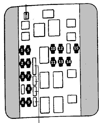
|
||
| No. | A | Protected Circuit |
| 1 | 10 | Hazard warning lights / Alarm |
| 2 | 20 | EFI engine ECU |
| 3 | 10 | Ignition switch (AM2) |
| 4 | 15 | Engine ECU (IG2 circuit) |
| 5 | 10 | Horn |
| 6 | 7.5 | Alternator |
| 7 | 7.5 | EFI engine ECU No. 1 |
| 8 | 7.5 | SRS airbag system |
| 9 | 30 | Fuel cut-off / CUT relay |
| 10 | 10 | Right low-beam headlight |
| 11 | 25 | Anti-lock braking system (ABS) |
| 12 | 10 | Left low-beam headlight |
| 13 | 7.5 | EFI engine ECU No. 2 |
| 14 | 10 | Right high-beam headlight |
| 15 | 10 | Left high-beam headlight |