Most of the power circuits of the electrical equipment of the Japanese sedan are protected by fuses. Headlamps, fan motors, fuel pump and other powerful current consumers are connected via relays. Protective elements are installed in mounting blocks, which are located in the engine compartment and the passenger compartment.

Fuse diagrams are relevant for Toyota Windom (V30) models 2001, 2002, 2003, 2004, 2005, 2006 with a 1MZ-FE engine (3.0 l).
In the passenger compartment
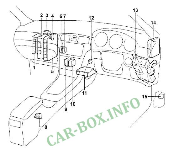
Location of components (dashboard). 1 - ABS control unit, 2 - audio system amplifier, 3 - rear fog lamp relay, 4 - acceleration sensor (front). 5 - electronic engine control unit, 6 - connector No. 9, 7 - connector No. 10, 8 - lateral movement sensor and deceleration sensor, 9 - wiper interval adjustment relay, 10 - headlight range control unit, 11 - SRS electronic control unit , 12 - buzzer of the stability control system (VSC), 13 - mounting block under the dashboard, 14 - TEMS electronic unit, 15 - direction indicator relay-interrupter.
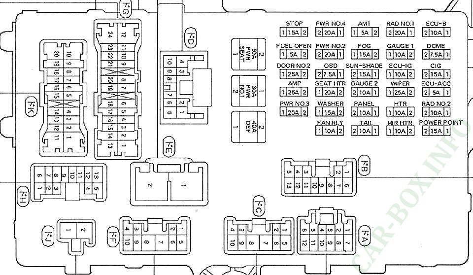
Fuse box
No. 13 on the picture above.

General view.
| Diagram | ||
|---|---|---|

|
||
| Code | Decoding | A |
| ECU ACC |
|
5 |
| AM 1 |
|
5 |
| FUEL OPEN |
Fuel filler flap opening system | 5 |
| OBD |
|
7.5 |
| DOME |
|
7.5 |
| ECU-B |
|
10 |
| ECU-IG |
|
10 |
| FAN RLY |
|
10 |
| GAUGE1 |
|
10 |
| GAUGE2 |
|
10 |
| MIR HTR |
|
10 |
| HTR |
|
10 |
| PANEL |
|
10 |
| TAIL |
|
10 |
| RAD # 2 |
Audio and navigation system | 10 |
| CIG | Cigarette lighter and socket for connecting additional equipment | 15 |
| FOG | Fog lamps | 15 |
| POWER POINT | Cigarette lighter and socket for connecting additional equipment | 15 |
| STOP |
|
15 |
| SUN SHADE |
Electric rear curtain | 15 |
| WASHER | Windshield wiper and washer | 15 |
| PWR # 2 |
|
20 |
| PWR # 3 |
|
20 |
| PWR # 4 |
|
20 |
| RAD # 1 |
|
20 |
| SEAT HTR |
Seat heater | 20 |
| DOOR No. 2 |
|
25 |
| WIPER | Windshield wiper and washer | 25 |
| PWR # 1 |
|
30 |
| PWR SEAT |
|
30 |
| DEF |
|
40 |
In the engine compartment
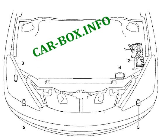
Location of components (engine compartment).
- fuse box,
- relay box,
- uzzer for central locking system,
- 4elay box (ABS),
- front airbag sensor.
Fuse box
No. 1 in the picture above.
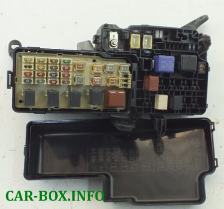
General view.
| Diagram | ||
|---|---|---|

|
||
| The code | Decoding | A |
| ALT-S | Charging system | 5 |
| ST | Instrument cluster | 5 |
| HEAD RH UPR |
|
10 |
| HEAD LH UPR |
|
10 |
| HORN |
|
10 |
| HAZ | Direction indicators and hazard warning lamps | 15 |
| IG2 |
|
10 |
| IGN |
|
15 |
| EFI |
|
20 |
| DOOR1 |
|
25 |
| AM2 |
|
30 |
| CDS | Fan electric drive | 30 |
| FR DEF | De-icer brushes | 30 |
| RDI | Fan electric drive | 30 |
| ABS No. 2 |
Anti-lock braking system (ABS) | 40 |
| ABS No. 3 |
40 | |
| MAIN |
|
40 |
| HTR | Automatic air conditioner | 50 |
Relay box
No. 2 on the picture above.
| Diagram | ||
|---|---|---|

|
||
| The code | Description | A |
| HEAD LH LWR |
|
15 |
| HEAD RH LWR |
15 | |
| ALT |
|
120 |
ABS box
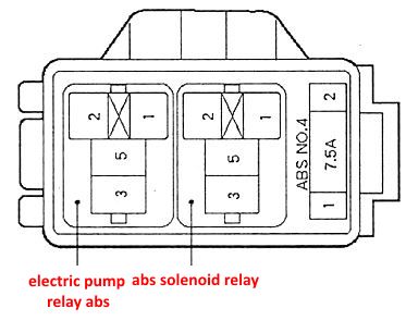
No. 4 on the picture.
