The first generation of Volvo's D-class sedan, the S40, was created in collaboration with Japan's Mitsubishi and shared a base with the Carisma, both cars being produced at the same NedCar plant in Holland. However, while sharing a common platform, the S40 has about 4,000 components out of 5,000 that differ. In this article, we will take a detailed look at the fuse box diagrams for the Volvo S40 (1st generation; codename VS) 1995, 1996, 1997, 1998, 1999, 2000, 2001, 2002, 2003, 2004 years of manufacture.
Here you will find the locations and photos of distribution boxes. The fuses responsible for the “Cigarette lighter” and “Fuel Pump” are highlighted in bold.
In the passenger comparment
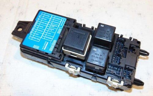
There are two distribution boxes here that are responsible for protecting the electrical circuits.
Fuse box
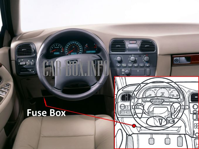
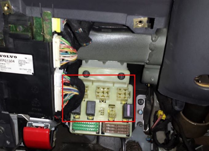
Located on the driver's side, at the bottom of the dashboard.
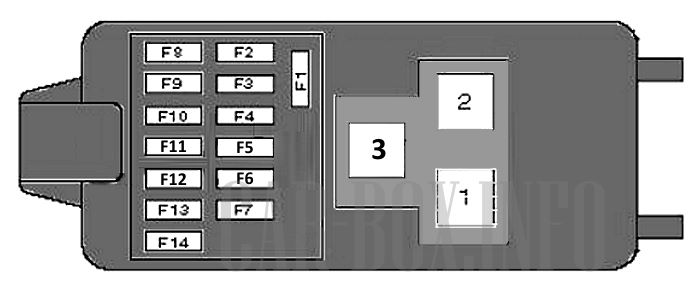
General view of the Volvo S40 interior fuse box.
| Diagram | ||
|---|---|---|
| No. | Description | A |
| Type No. 1 | ||
|
||
| F1 | heater / air conditioner | 25 |
| F2 | Accessory connector, cigarette lighter fuse volvo s40 | 10/20 |
| F3 | Anti-theft system, central locking, power seats, power window lifters, door mirror heaters | 10/20 |
| F4 | Anti-lock braking system (ABS), multifunction control unit | 10 |
| F5 | Seat heater | 20 |
| F6 | Anti-lock brakes (ABS), turn signal indicators/anti-theft system, multifunction control unit, reversing lights | 10 |
| F7 | Anti-theft system, automatic transmission control system, central locking, speed maintaining system, engine management system (LPG), instrument cluster indicators, light switch, seatbelt monitoring system, SRS system | 10 |
| F8 | Anti-theft system, central locking, direction indicators / emergency signalization | 15/20 |
| F9 | Audio system | 15 |
| F10 | Headlight wiper, windshield wiper / washer | 20 |
| F11 | Automatic transmission control system, central locking, engine management system, immobilizer, instrument cluster, SRS system | 10 |
| F12 | Anti-theft alarm system buzzer, rear window heater, heater/air conditioner, interior lamps, multifunction control unit, seatbelt monitoring system, sunroof | 15 |
| F13 | Diagnostic connector (DLC), brake lights | 15 |
| F14 | Headlight washer system, rear window washer / wiper system | 20 |
| # | Relay modules | |
| 1 | rearview mirror heater / rear window heater relay | |
| 2 | air conditioning | |
| 3 | turn signal interrupter | |
| Type No. 2 | ||

|
||
| F1 | Cooling fan motor, air conditioner | 25 |
| F2 | Spare | 20 |
| F3 | 10 | |
| F4 | Reverse lights, brake lights, traction control, electronic transmission control unit, transmission switch illumination lamp | 10 |
| F5 | Cruise control system, brake light switch, transmission switch illumination lamp | 10 |
| F6 | Seat heaters, rear interior lamps, license plate illumination lamp, illuminated light switch, fog lamps/lights and fog lamp/light switches, instrument cluster illumination rheostat | 20 |
| F7 | Illuminated door lock switch against accidental opening, instrument cluster, turn signal indicators, daytime running light system, trip computer, delayed switch-off of the interior lamp | 10 |
| F8 | Alarm | 20 |
| F9 | Audio system, power door mirrors, power windows, power antenna | 15 |
| F10 | Rear window wiper motor and washer pump (5-door) | 10 |
| F11 | SRS system, central locking, immobilizer, engine management system relay, fuel cut-off switch (diesel) | 10 |
| F12 | Sunroof, rear window and mirror heaters, headlights and headlight switch indicator, sun visor lamp | 15 |
| F13 | Parking lights, diagnostic connector power, headlight corrector, cigarette lighter fuse | 15 |
| F14 | Windshield wiper motor and wiper switch, headlight wipers, washer pump | 20 |
| # | Relay modules | |
| 1 | rear window heater | |
| 2 | heater fan motor | |
| 3 | turn signal interrupter | |
| 4 | delay in switching off the interior lamp | |
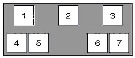
Relay box
To the left of the main fuse box is the passenger compartment relay box.
| Diagram | |
|---|---|
|
|
| No. | Decryption (Type 1) |
| 1 | Empty |
| 2 | trunk lid / rear door lock actuator - ^05/00, if available |
| 3 | unbelted seat belt warning system / ignition key warning system relay |
| 4 | starter - 06/00 ^ |
| 5 | power windows relay |
| 6 | starter - ^ 05/00 |
| 7 | Empty |
| No. | Decryption (Type 2) |
| 1 | central locking # 1 |
| 2 | central locking # 2, rear doors |
| 3 | rear window cleaner / washer |
| 4 | Empty |
| 5 | power windows |
| 6 | starter (immobilizer) |
| 7 | Empty |
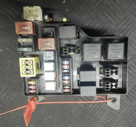
In the engine compartment

It is located near the rack. To access the fuses it is necessary to remove the protective cover by releasing the catches.
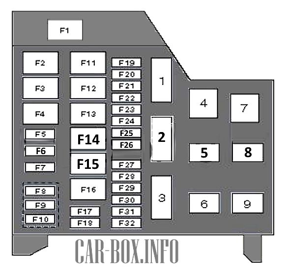
2000-2004 model year
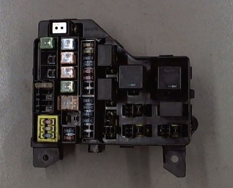
General view of the distribution box.
| Diagram | ||
|---|---|---|
|
||
| No. | Description | A |
| F1 | Alternator (Diesel), F2-10, glow plugs | 120 |
| F2 | Passenger compartment fuse box (F1-2, F8 and F13) | 40 |
| F3 | Coolant Heater Relay # 1 / # 2 (Diesel) | 30 |
| F4 | 30 | |
| F5 | Rear view mirror heater, rear window heater | 25 |
| F6 | Power seat (driver's) | 25 |
| F7 | Power passenger seat | 25 |
| F8 | Air conditioning, anti-theft system, central locking, power antenna, engine management system (Melco), instrument cluster, interior lamps | 10 |
| F9 | Anti-theft system, central locking | 20 |
| F10 | Audio system | 15 |
| F11 | Engine management system, immobilizer | 20 |
| F12 | Power door mirrors, power windows | 30 |
| F13 | Cooling fan motor | 30 |
| F15 | Anti-lock braking system (ABS) | 50 |
| F16 | Empty | |
| F17 |
|
15 |
| F18 | Air conditioner compressor solenoid clutch relay (Diesel), coolant heater relay 1/2 (Diesel), engine management system | 10 |
| F19 | Fog lights and lights | 20 |
| F20 | Empty | |
| F21 | Left headlight - dipped beam | 15 |
| F22 | Right headlight - dipped beam | 15 |
| F23 | Front / rear position light bulbs | 10 |
| F24 | Headlight corrector, license plate illumination lamps, front/rear parking lamps | 10 |
| F25 | Automatic transmission control system, engine management system (LPG) | 10 |
| F26 | Alternator (Melco) | 10 |
| F27 | Accessory Power Connector - Rear | 15 |
| F28 | Left headlight - high beam, right headlight - high beam | 15 |
| F29 | Horn | 15 |
| F30 | A/C compressor solenoid relay, A/C condenser fan motor (Melco & EMS2000 Turbo) | 15/20 |
| F31 | Brake booster vacuum pump (automatic transmission) | 15 |
| F32 | Empty | |
| # | Relay modules | |
| 1 | Cooling system fan motor #1 | |
| 2 | A / C Compressor Electromagnetic Clutch | |
| 3 | air conditioner condenser fan motor | |
| 4 | cooling fan motor #2 (Diesel, Turbo and EMS2000) | |
| 5 | Empty | |
| 6 | brake booster vacuum pump (EMS 2000 Turbo with automatic transmission) | |
| 7 | engine management system | |
| 8 | Horn | |
| 9 | coolant heater No. 2 (Diesel) | |
1995-05.2000 model year
General view.
| Diagram | ||
|---|---|---|
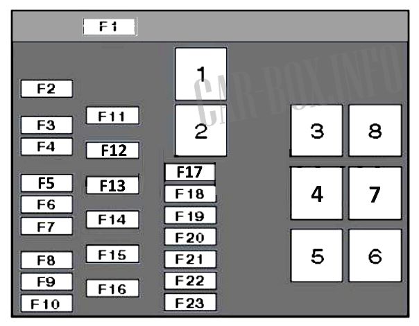
Diagram. |
||
| No. | Description (Type 1) | A |
| F1 | Alternator, F2-7, glow plugs, exhaust air pump motor | 120 |
| F2 | Interior fuse box (F1-2, F8 and F13) | 40/50 |
| F3 | Door mirrors and rear window heater | 25 |
| F4 | Anti-theft system, power seats, fog lights, horn | 20/30 |
| F5 | Anti-theft system, audio system, central locking, immobilizer, instrument cluster, interior lighting lamps | 10 |
| F6 | Anti-theft system, central locking, door locking system against accidental opening - rear door | 20 |
| F7 | air conditioning | 15/20 |
| F8 | Alternator (B4184SM), fog lights and lamps | 20 |
| F9 | Air conditioning, left headlight - low beam, multifunction control unit | 10/15 |
| F10 | Multifunctional control unit, right headlight - low beam, brake lights | 10/15 |
| F11 | Coolant Heater (Diesel), Ignition Switch | 40/50 |
| F12 | Anti-lock braking system (ABS) | 50 |
| F13 | Engine management | 50 |
| F14 | Ignition lock | 40 |
| F15 | Air conditioning system, cooling fan motor | 30 |
| F16 | Power windows | 30 |
| F17 | Anti-theft system, horn | 15 |
| F18 | Front / rear side light bulbs | 10 |
| F19 | Left headlight - high beam, multifunction control unit, right headlight - high beam | 15 |
| F20 | Fuel pump fuse | 15 |
| F21 | Engine management | 10/20 |
| F22 | Alternator, brake booster vacuum pump (models with turbocharged petrol engine and automatic transmission) | 15 |
| F23 | Headlights corrector | 10 |
| # | Relay modules | |
| 1 | air conditioning compressor electromagnetic clutch | |
| 2 | cooling fan motor No. 2 (Diesel) | |
| 3 | cooling fan motor No. 1 | |
| 4 | Fuel pump relay (Melco 1) | |
| 5 | starter | |
| 6 | air conditioner condenser fan motor (petrol) | |
| 7 | cooling fan motor 2 (EMS 2000) | |
| 8 | engine management system (Diesel and EMS 2000) | |
| No. | Description (Type 2) | A |
| F1 | Alternator, Power to Fuses 2,4,5,6 & 7, Exhaust Air Pump, Glow Plugs (Diesel) | 120 |
| F2 | Power to the under-dash fuse box | 40 |
| F3 | Heated rear window, heated mirrors | 25 |
| F4 | Horn, fog lights, anti-theft alarm LED | 20 |
| F5 | Power supply for central locking remote control, audio system memory, trip computer, instrument cluster, immobilizer, clock, interior lighting lamps, rear local lamps, ignition switch / trunk / duffel box illumination lamps | 10 |
| F6 | Electric actuators of the central locking remote control system and fault indicator | 20 |
| F7 | Not used | - |
| F8 | Not used | - |
| F9 | Air conditioning compressor | 10 |
| F10 | Stop lights | 10 |
| F11 | Ignition switch, cruise control, fuel restriction valve | 40 |
| F12 | ABS system | 50 |
| F13 | Engine components | 20 |
| F14 | Low / high beam headlights | 20 |
| F15 | Cooling fan, air conditioner condenser fan | 30 |
| F16 | Front and rear power windows | 30 |
| F17 | Fuel pump fuse Volvo S40 | 10 |
| F18 | Oxygen sensor heater | 10 |
| F19 | Not used | - |
| F20 | Not used | - |
| F21 | Not used | - |
| F22 | Not used | - |
| F23 | ABS ECU | 10 |
| # | Relay modules | |
| 1 | Air conditioner compressor solenoid clutch | |
| 2 | Air intake switch damper motor (air conditioner) | |
| 3 | Not used | |
| 4 | cooling fan motor | |
| 5 | Headlights | |
| 6 | air conditioner condenser fan motor | |
| 7 | Alarm (horn relay) | |
| 8 | Engine ECU | |

i find the daigrams of the fuse box not very clear. Is there a simplier plan for a lay man like me I have a s40 saloon a late registeration in 1999 model can you help me please I will be most gratefulmany thanks c.m.brammah