The first generation of the Volvo XC90 luxury crossover was introduced in 2002. Together with the S60, V70 and S80 models, it was built on the P2 platform. For its time, it became the largest among the crossovers produced by the company. In this article, we will take a detailed look at the fuse box diagrams for the Volvo xc90 (1st generation; codename C) 2002, 2003, 2004, 2005, 2005, 2006, 2007, 2007, 2008, 2008, 2009, 2009, 2010, 2011, 2012, 2012, 2013, 2014 years of manufacture.

Here you will find the locations and photos of distribution boxes. The fuses responsible for the “Cigarette lighter” and “Fuel Pump” are highlighted in bold.
Block layout
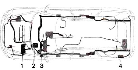
The fuse distribution boxes are located in four locations.
1. in the engine compartment.
2. in the passenger compartment behind the soundproof trim on the driver's side.
3. in the passenger compartment at the end of the dashboard on the driver's side.
4. in the luggage compartment.
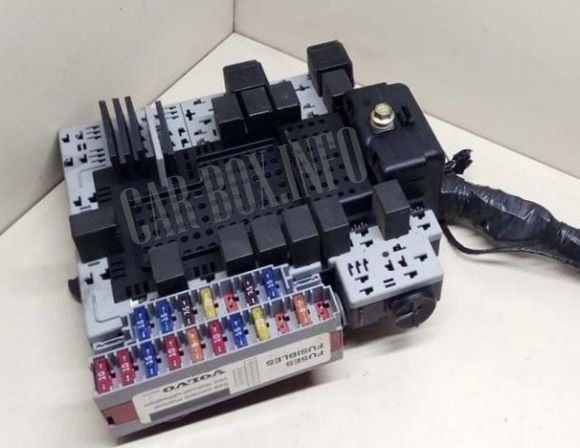
In the engine compartment
Fuse box
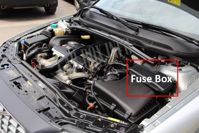
To access the fuses, press the plastic catches on the short sides of the unit and pull the cover up.
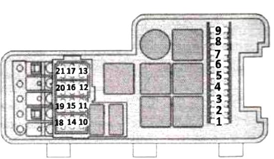
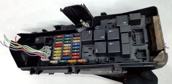
Type 1
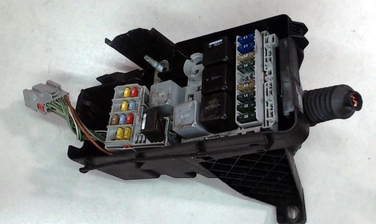
General view (type 1).
| Diagram | ||
|---|---|---|
|
||
| No. | Description | A |
| 1 | ABS | 30 |
| 2 | ABS | 30 |
| 3 | High-pressure headlight washers | 35 |
| 4 | Parking heater (optional) | 25 |
| 5 | Additional headlights (optional) | 20 |
| 6 | Starter relay | 35 |
| 7 | Windshield wipers | 25 |
| 8 | Fuel pump fuse Volvo XC90 | 15 |
| 9 | Transmission Control Module (TCM), (V8, diesel, 6-cyl. gasoline) | 15 |
| 10 | Ignition coils (gasoline), engine control module (ECM), injector valves, (diesel) | 20 |
| 11 | Fuel pedal position sensor (FPS), AC compressor, fan, electronic unit | 10 |
| 12 | Engine Control Module (ECM) (gasoline), injectors, (gasoline), air flow meter (gasoline); air flow meter (diesel) | 15, 5 |
| 13 | Throttle control module (V8), V1S (6-cyl. gasoline); throttle control module, solenoid valve, SWIRL (air mixture valve), fuel pressure regulator (diesel) | 10, 15 |
| 14 | Lambda probe (gasoline); lambda probe (diesel) | 20, 10 |
| 15 | Crankcase ventilation heater, solenoid valves, leak diagnostics (5-cyl. gasoline); Crankcase ventilation heater (V8, 6-cyl. gasoline), AC clutch (V8, 6-cyl. gasoline), solenoid valves, leak diagnostics (V8, 6-cyl. gasoline), ECM, (V8, 6-cyl. gasoline), air flow meter (V8), glow plugs (diesel) | 10, 15 |
| 16 | Dipped beam headlights, left | 20 |
| 17 | Dipped beam headlights, right | 20 |
| 18 | Reserve socket | |
| 19 | Engine control unit (ECM), power, engine relay | 5 |
| 20 | Position lights | 15 |
| 21 | Reserve socket | |
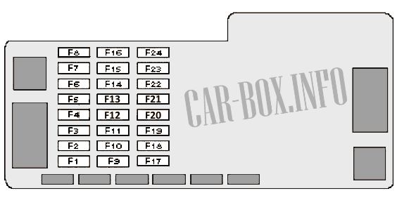
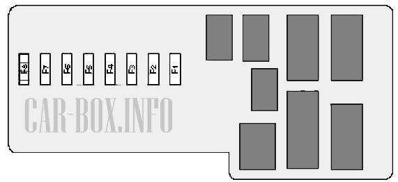
Type 2
General view.
| Diagram | ||
|---|---|---|
|
||
| No. | Decoding | A |
| F1 | Additional heater control unit | 25 |
| F2 | Extra equipment | 20 |
| F3 | Engine management - Bi-fuel, vacuum pump (2002) | 15 |
| F4 | Heated oxygen sensors, engine management (Diesel) | 20 |
| F5 | Engine management system (petrol) | 15 |
| F6 | 15 | |
| F7 | - | |
| F8 | Accelerator pedal position sensor, air conditioner compressor solenoid clutch relay, cooling fan fuse box/relay | 10 |
| F9 | Horn (beep) | 15 |
| F10 | Rear window washer pump electric motor | 10 |
| F11 | Engine Management, Glow Plugs, HVAC System, Crankcase Ventilation Heater (Diesel) | 20 |
| F12 | Stop lights | 5 |
| F13 | Windshield wiper | 25 |
| F14 | Anti lock brake system ABS / ESP (DST C) | 30 |
| F15 | Headlamp washer/wiper system | 25 |
| F16 | Windshield washer pump motor | 15 |
| F17 | Right headlight - dipped beam (xenon) | 10 |
| F18 | Left headlight - dipped beam xenon) | 10 |
| F19 | Anti-lock braking system ABS / ESP (DSTС) | 30 |
| F20 | Left headlight - high beam | 15 |
| F21 | Right headlight - high beam | 15 |
| F22 | Starter | 25 |
| F23 | Engine control relay, electronic engine control unit (ECM) | 5 |
| F24 | - | |
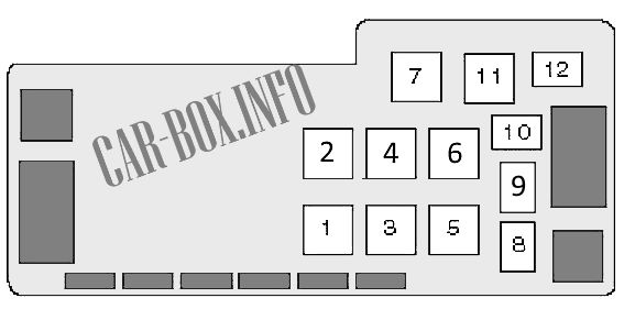
| The purpose of the relay in the block | |
|
|
| 1 | - |
| 2 | Engine management system |
| 3 | Glow plugs |
| 4 | Starter |
| 5 | Intermittent operation of the windshield wiper |
| 6 | Headlight washer / wiper |
| 7 | - |
| 8 | A / C Compressor Electromagnetic Clutch |
| 9 | Horn |
| 10 | Windshield washer pump |
| 11 | Windshield wiper motor |
| 12 | Rear window washer pump motor |
Power fuses
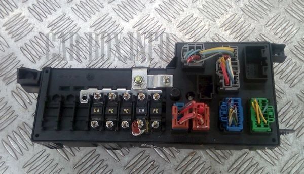
Located on the back of the unit.
| Diagram | ||
|---|---|---|
|
||
| No. | Decoding | A |
| F1 | Glow plugs | 60 |
| F2 | Passenger compartment block #1: fuses (F5-7), (F25-27), (F32-33) | 60 |
| F3 | Passenger compartment block #1: fuses (F3-4), (F8-11), (F16-19), (F34-38) | 60 |
| F4 | Passenger compartment block #1: fuses (F1), (F12-15), (F20-24) | 60 |
| F5 | Empty | |
| F6 | Empty | |
| F7 | Empty | |
| F8 | Cooling fan motor | 60 |
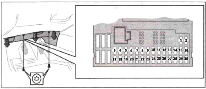
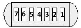
In the passenger compartment
From the end of the dashboard
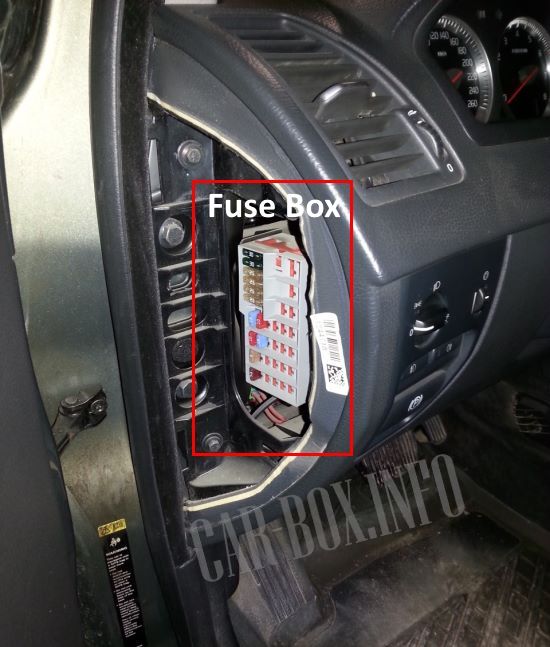
It is located behind the soundproof panel on the driver's side. A label indicating the fuse position and ampere rating is located under the end block cover.
| Diagram | ||
|---|---|---|
|
||
| No. | Description | A |
| 1 | Air conditioner fan | 30 |
| 2 | Audio system (amplifiers) | 30 |
| 3 | Electric driver's seat | 25 |
| 4 | Electric passenger seat | 25 |
| 5 | Left control unit, front door | 25 |
| 6 | Right control unit, front door | 25 |
| 7 | Reserve | - |
| 8 | Radio, CD player, RSE system | 15 |
| 9 | RTI display, MMM RTI module | 10 |
| 10 | OBDII, light switch (LSM), steering angle sensor (SAS), steering wheel control module (SWM) | 5 |
| 11 | Ignition switch, SRS system, ECM engine control module (V8, 6-cyl. gasoline) passenger-side SRS disable (PACOS), electronic start interlock (IMMO), TCM transmission control module (V8, diesel, 6-cyl. gasoline) | 7.5 |
| 12 | General lighting, ceiling mounted (RCM), overhead electronic control module (UEM) | 10 |
| 13 | Sunroof | 15 |
| 14 | Telephone | 5 |
| 15-38 | Reserve sockets | |
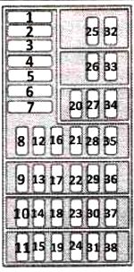
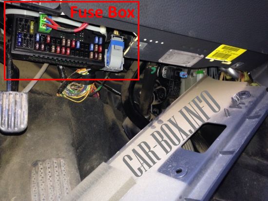
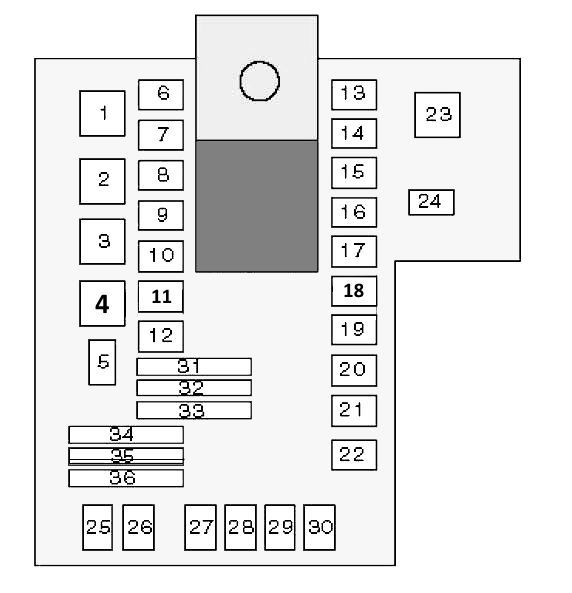
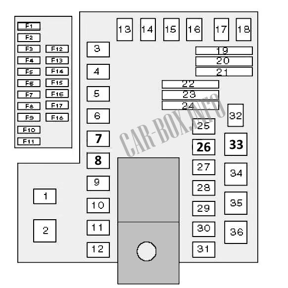
Behind the bottom panel

To gain access, unscrew the two retaining screws and remove the trim panel.
Access example.
| Diagram | ||
|---|---|---|
|
||
| No. | Description | A |
| 1 | Heated seat, right side | 15 |
| 2 | Seat heating, left side | 15 |
| 3 | Horn (beep) | 15 |
| 4 | Reserve | - |
| 5 | Infotainment system | 10 |
| 6 | Reserve | - |
| 7 | Reserve | - |
| 8 | Alarm siren | 5 |
| 9 | Brake signal contacts, power supply | 5 |
| 10 | Combined instrumentation (DIM), climate control system (CCM), parking heater, power driver's seat | 10 |
| 11 |
|
15 |
| 12 | Reserve | - |
| 13 | Reserve | - |
| 14 | Reserve | - |
| 15 | ABS, STC / DSTC | 5 |
| 16 | Electronic servo control (ECPS), active bi-xenon (ABC), headlight beam height adjustment | 10 |
| 17 | Fog lamp, front left | 7.5 |
| 18 | Fog lamp, front right | 7.5 |
| 19 | Reserve | |
| 20 | Coolant pump (V8) | 5 |
| 21 | Communication control unit (TOM), reverse gear lock (M66) | 10 |
| 22 | High beam headlights, left | 10 |
| 23 | High beam headlights, right | 10 |
| 24 | Reserve | |
| 25 | Reserve | |
| 26 | Reserve | |
| 27 | Reserve | |
| 28 | Electrically operated passenger seat | 5 |
| 29 | Fuel pump fuse | 7.5 |
| 30 | BUS | 5 |
| 31 | Reserve socket | |
| 32 | Reserve socket | |
| 33 | Vacuum pump | 20 |
| 34 | Washer fluid pump | 15 |
| 35 | Reserve | |
| 36 | Reserve | |
Relay box
The board is located behind the bottom panel above the main unit.
| Diagram | |
|---|---|
|
|
| No. | Relay module |
| 1 | - |
| 2 | Auxiliary ignition circuits |
| 3 | Main ignition circuits |
| 4 | - |
| 5 | - |
| 6 | power window elevator - closing, left rear door |
| 7 | power window elevator - opening, left rear door |
| 8 | disabling the rear window elevator motors, locking the doors against accidental opening - rear doors |
| 9 | high beam headlights |
| 10 | Parking lamps |
| 11 | Daytime lighting system |
| 12 | Dipped beam headlights |
| 13 | Power Window Relay - Close, RH |
| 14 | Power Window Relay - Opening, RH Door |
| 15 | Relay 2 auxiliary ignition circuits |
| 16 | Transmission control system |
| 17 | - |
| 18 | - |
| 19 | - |
| 20 | - |
| 21 | Telematics |
| 22 | - |
| 23 | - |
| 24 | - |
| 25 | - |
| 26 | - |
| 27 | Fog lights |
| 28 | Fuel pump relay Volvo XC90 |
| 29 | - |
| 30 | Fuel leakage control relay |
| 31 | Jumper - left direction indicators |
| 32 | Jumper - right direction indicators |
| 33 | - |
| 34 | Jumper - dipped beam headlights |
| 35 | - |
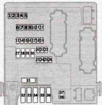
In the trunk
Fuse box
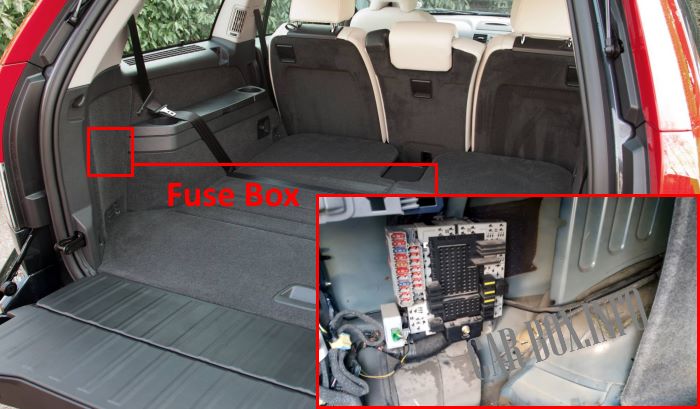
Located behind the trim on the left side of the luggage compartment. On Executive versions, an auxiliary board may be mounted next to it.
Type 1
General view of the Volvo XC90 trunk fuse box.
| Diagram | ||
|---|---|---|
|
||
| No. | Description | A |
| 1 | Reversing light | 10 |
| 2 | Parking lights, fog lights, luggage compartment lights, license plate lights, brake lights | 20 |
| 3 | Accessories (AEM) | 15 |
| 4 | Reserve | - |
| 5 | Electronic equipment REM | 10 |
| 6 | Rear Seat Entertainment RSE (Accessory) | 7.5 |
| 7 | Wiring (30 power) | 15 |
| 8 | Electrical socket in the luggage compartment | 15 |
| 9 | Rear door, right: power window, power window lock | 20 |
| 10 | Tailgate, LH: Power Window, Power Window Lock | 20 |
| 11 | Reserve | - |
| 12 | Reserve | - |
| 13 | Diesel filter heater | 15 |
| 14 | Subwoofer, rear air conditioning (A / C) | 15 |
| 15 | Reserve | - |
| 16 | Reserve | - |
| 17 | Additional audio equipment | 5 |
| 18 | Reserve | - |
| 19 | Rear cleaner | 15 |
| 20 | Wiring (15 power) | 20 |
| 21 | Reserve | - |
| 22 | Reserve | - |
| 23 | AWD | 7.5 |
| 24 | Reserve | - |
| 25 | Reserve | - |
| 26 | Parking assistance | 5 |
| 27 | Main fuse: wiring to trailer, park assist, AWD | 30 |
| 28 | Central locking (PCL) | 15 |
| 29 | Trailer lighting on the left side: parking lights, direction indicators | 25 |
| 30 | Trailer lighting on the right side: brake light, rear fog lights, direction indicators | 25 |
| 31 | Main fuse | 40 |
| 32 | Reserve socket | |
| 33 | Reserve socket | |
| 34 | Reserve socket | |
| 35 | Reserve socket | |
| 36 | Reserve socket | |
| 37 | Electrically heated rear window | 20 |
| 38 | Electrically heated rear window | 20 |
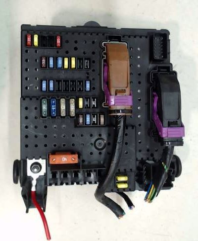
Type 2
General view.
| Diagram | ||
|---|---|---|
|
||
| No. | Description | A |
| F1 | Multifunction control unit 2, interior luggage compartment illumination-lighting | 10 |
| F2 | Rear fog lights | 10 |
| F3 | Stop lights | 15 |
| F4 | Back-up lights | 10 |
| F5 | Rear window heater, trailer electrical connector power relay | 5 |
| F6 | Rear door opening actuator | 10 |
| F7 | Accessory Power Connector - Luggage Compartment | 15 |
| F8 | Central locking - locking rear side doors / rear door hatch / fuel filler flap | 15 |
| F9 | Trailer electrical connector | 20 |
| F10 | Antenna signal amplifier | 5 |
| F11 | Extra equipment | 15 |
| F12 | Rear window wiper motor | 15 |
| F13 | Audio system, air conditioning / heating system - rear | 15 |
| F14 | Stop lights | 7.5 |
| F15 | Trailer electrical connector | 20 |
| F16 | Not used (2002) | |
| F17 | Fuel filter heater (Diesel), differential lock control unit | 7.5 |
| F18 | Fuel filter heater (diesel) | 15 |
| 1 | - | |
| 2 | - | |
| 3 | - | |
| 4 | Relay for intermittent operation of the rear window wiper | |
| 5 | Bi-fuel relay | |
| 6 | A / C ECU Relay - Rear A / C | |
| 7 | Rear door drive relay | |
| 8 | Not used (2002) | |
| 9 | Fuel filler neck fuel lock actuator relay - opening | |
| 10 | - | |
| 11 | Right rear door central locking relay - unlocking | |
| 12 | - | |
| 13 | - | |
| 14 | Rear wiper motor relay | |
| 15 | - | |
| 16 | - | |
| 17 | - | |
| 18 | - | |
| 19 | Jumper - brake lights | |
| 20 | Jumper - rear position lights | |
| 21 | Jumper - rear position lights | |
| 22 | Jumper - auxiliary equipment power connector in the luggage compartment | |
| 23 | Jumper - fog lights | |
| 24 | - | |
| 25 | Rear Fog Lamp Relay - Trailer | |
| 26 | Rear fog lamp relay | |
| 27 | Brake light relay | |
| 28 | Back-up lamp relay | |
| 29 | Central locking relay, rear - double interlocking | |
| 30 | Left rear door central locking relay - unlocking | |
| 31 | Fuel filler flap lock actuator relay - closing, central lock relay - rear doors - closing (2002) | |
| 32 | Fuel filter heater relay (diesel) | |
| 33 | - | |
| 34 | Rear window heater relay | |
| 35 | Audio system | |
| 36 | Trailer electrical connector power relay | |
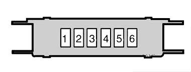
Accessory box
Installed only on Executive version.
| Diagram | ||
|---|---|---|
|
||
| No. | Appointment | A |
| 1 | Rear seat heating and front seat massage relay | 5 |
| 2 | Rear driver's seat heating | 15 |
| 3 | Heated rear seat on the passenger side | 15 |
| 4 | Front seat ventilation / massage | 10 |
| 5 | Empty | - |
| 6 | Empty | - |
Power fuse panel
Located near the battery.
| Diagram | ||
|---|---|---|
|
||
| No. | Description | A |
| 1 | Luggage fuse box circuits (F15-18) | 40 |
| 2 | Luggage fuse box circuits (F12-13) | 40 |
| 3 | Rear window heater | 40 |
| 4 | Empty | - |
| 5 | Luggage fuse box circuits (F6-11) | 40 |
| 6 | Empty | - |
| 7 | Luggage fuse box circuits (F1-5) | 40 |
General arrangement
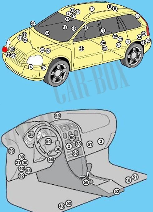
Location of all electronic modules in Volvo XC90.
1. Optional equipment ECU-right side of the luggage compartment;
2. Air conditioner ECU - behind the air conditioner control panel;
3. Air conditioner/heater fan control unit - next to the fan motor;
4. Antenna unit, telephone;
5. Antenna signal amplifier - ceiling panel;
6. Impact sensor, left;
7. Impact sensor, right;
8. Safety curtain igniter, left.;
9. Safety curtain igniter. Right.;
10. Side impact sensor assembly - driver's side center pillar.;
11. Side impact sensor, rear left - behind rear seat cushion support.;
12. Side impact sensor assembly - center pillar on passenger side;
13. Side impact sensor, rear right - behind the rear seat cushion support;
14. Vehicle tilt sensor (anti-theft system);
15. Anti-theft alarm system horn - behind the front right wheel arch lining;
16. Volume change sensor (anti-theft system) - roof panel;
17. Antitheft alarm sensor - in multifunction control module 3;
18. Audio output amplifier;
19. Additional heater control module, if fitted;
20. Battery pack - under the luggage compartment floor;
21. Speed maintenance control module integrated in the electronic engine control unit.;
22. Diagnostic connector (DLC);
23. Differential lock control module - on the rear differential;
24. Passenger door electrical control module- in the door - functions: Central locking, open or loose door indicators, power/heated; door mirrors, power windows, light bulbs in door mirrors, outside temperature;
25. Driver's door electrical control module in the driver's door-functions: Central locking, open or loose door indicators, power/heated door mirrors on doors, power windows, light bulbs in door mirrors, outside temperature;
26. Cooling fan motor control module;
27. Fuse box, engine compartment 1;
28. Fuse box 2 - under engine compartment fuse box 1;
29. Fuse box at the end of the dashboard;
30. Fuse box at the bottom of the dashboard;
31. Fuse/relay box, luggage compartment 1;
32. Power fuse box 2 - next to the battery;
33. Heater ECU - behind the heater controls;
34. Horn - behind the front bumper;
35. Immobilizer - in the electronic engine control unit;
36. Immobilizer ring antenna - near ignition switch;
37. Turn signal/emergency signaling relay - in the multifunction control unit 1;
38. Instrument cluster control module - instrument panel;
39. Lighting control module - behind the headlight switch;
40. Multifunction control unit 1 - connected with fuse box/relay 2 instrument panel - functions: Anti-theft system, central locking power windows, windshield wiper/washer, headlight wiper/washer, power steering, immobilizer, headlights, turn signal/emergency warning lights, horn, front/rear parking lights, starter, seat heating, headlight corrector, fuel pump, duffel box illumination lamp;
41. Multifunction control unit 2- connected by fuse/relay box, luggage compartment 1 - functions: Anti-theft system, central locking, tail lights, fuel level, interior lamps, rear window wiper/washer, rear window heater, auxiliary equipment power connectors - rear, parking system, fuel filter heater - Diesel;
42. Multifunction control unit 3-functions: Central locking, anti-theft system, sunroof, rain sensor, interior lamps, unbuckled seat belt reminder;
43. Navigation system control module - under the left-hand seat;
44. Ambient air temperature sensor - in the right-hand door mirror;
45. Parking system control module;
46. Power steering relay;
47. Rain sensor (if fitted);;
48. Relay for door locking system against accidental opening, left. - in the door;
49. Door lock relay, right - in the door;
50. Driver's power seat control module - under the seat;
51. Seat occupant sensor - in the seat cushion;
52. SRS ECU;
53. Steering wheel position sensor module - connected to fuse box/relay 2 under the instrument panel;
54. Steering wheel electrical control unit - behind the steering wheel - functions: Audio system, speed maintaining system (cruise control),horn .turn indicators, windshield wiper/washer, rear window wiper/washer, low beam/distance beam headlights;
55. Sunlight sensor;
56. Sunroof control module - in multifunction control unit 3;
57. TRANSMISSION ECU;
59. Telematics module - functions: Audio system, telephone;
60. Telephone control module, hands-free;
61. Telephone interface control module - behind the air conditioning control panel.

cx 90 2007 is not there