The Volvo S80 sedan was introduced in 1998. It was developed entirely by Volvo engineers and embodies a new design approach. The model shows streamlined forms with expressive front and rear optics, and the wide and almost flat shoulder line, has become one of the car's hallmarks. In this article, we will take a detailed look at the fuse box diagrams for the Volvo S80 (codename TS) 1998, 1999, 2000, 2001, 2002, 2003, 2004, 2005, 2006 years of manufacture.

Here you will find the locations and photos of distribution boxes. The fuses responsible for the “Cigarette lighter” and “Fuel Pump” are highlighted in bold.
In the passenger compartment
There are two distribution boxes here that are responsible for protecting the electrical circuits.
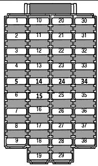
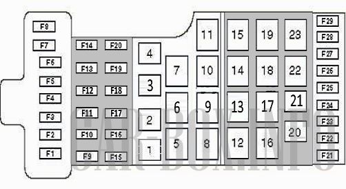
Fuse box
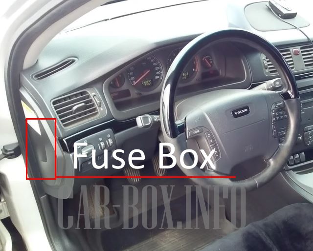
Located at the end of the dashboard on the driver's side.
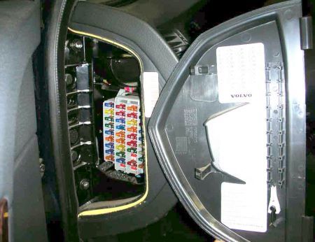
Example of block access.
| Diagram | ||
|---|---|---|
|
||
| No. | Description (models from 04.2000 onwards) | A |
| F1 | Left headlight - dipped beam | 10 |
| F2 | Right headlight - dipped beam | 10 |
| F3 | Dipped beam relay | 15 |
| F4 | High beam relay | 20 |
| F5 | Power seat - driver's side | 30 |
| F6 | Power seat - passenger side | 30 |
| F7 | Heated front left seat | 15 |
| F8 | Heated front right seat | 15 |
| F9 | ABS system, steering position control system unit | 5 |
| F10 | Left headlight - high beam | 15 |
| F11 | Right headlight - high beam | 15 |
| F12 | Headlamp washer/wiper system, headlamp corrector | 15 |
| F13 |
|
20 |
| F14 | Power seat on the passenger side, SRS system, seatbelt monitoring system | 5 |
| F15 | Audio system, navigation system | 5 |
| F16 | Audio system | 20 |
| F17 | Audio system output amplifier | 30 |
| F18 | Fog lights | 15 |
| F19 | Navigation system | 10 |
| F20 | Extra equipment | 5/15 |
| F21 | Automatic transmission | 10 |
| F22 | Direction indicators / emergency warning lights | 20 |
| F23 | Air conditioning / heater control unit, combined switch-lighting switch, diagnostic connector, steering wheel switches | 5 |
| F24 | Air conditioning / heater ECU, auxiliary heater, power seat drive - driver's side, instrument cluster | 10 |
| F25 | Ignition switch, multifunction control unit 1 | 10 |
| F26 | Air conditioner / heater fan motor control module | 30 |
| F27 | Central locking, open or loose door indicators, electric / heated door mirrors, power windows, light bulbs in door mirrors | 15 |
| F28 | Multifunction control box 3, interior lamps, cosmetic mirror | 10 |
| F29 | Telephone | 10 |
| F30 | Front left parking light bulb, rear left parking light bulb, side left parking light bulb | 10 |
| F31 | Front/rear position lamps (right), right side position lamp, number plate illumination lamps | 10 |
| F32 | 1 multifunctional control unit, interior lamps, cosmetic mirror | 10 |
| F33 | Fuel pump fuse | 15 |
| F34 | Sunroof | 15 |
| F35 | Front left-hand side - central locking, power window, power door mirrors, open or loose door indicators | 25 |
| F36 | Front right-hand side - central locking, power window, power door mirrors, open or loose door indicators | 25 |
| F37 | Rear window motors, door locks against accidental opening - rear door | 30 |
| F38 | Audible alarm of the anti-theft system | 5 |
| No. | Description (models up to 04.2000) | A |
| F1 | Left headlight - dipped beam | 10 |
| F2 | Right headlight - dipped beam | 10 |
| F3 | Fog lights | 15 |
| F4 | Power seat - driver's side | 30 |
| F5 | Power seat - passenger side | 30 |
| F6 | - | |
| F7 | Relay 1 of ignition auxiliary circuits, multifunction control unit 1, SRS system, seatbelt monitoring system (^01/99) | 5 |
| F8 | Heater for front seats | 25 |
| F9 | ABS system, steering wheel position control unit | 5 |
| F10 | Left headlight - high beam | 15 |
| F11 | Right headlight - high beam | 15 |
| F12 | Headlamp washer / wiper system, headlamp corrector | 15 |
| F13 | Charging socket and cigarette lighter fuse | 20 |
| F14 | Power seat on the passenger side, SRS(02/99^), seatbelt monitoring system (02/99^). | 5 |
| F15 | Audio system, navigation system | 5 |
| F16 | Audio system | 20 |
| F17 | Audio system output amplifier | 30 |
| F18 | Telephone, navigation system | 10 |
| F19 | Reserve | |
| F20 | Reserve | |
| F21 | Direction indicators / emergency warning lights | 20 |
| F22 | Switches on the steering wheel - telephone / Cruise Control | 5 |
| F23 | Air conditioning and heater control module, combination switch - lighting, diagnostic connector | 5 |
| F24 | Air conditioning / heater ECU, auxiliary heater control unit, power seat drive - driver's side, instrument cluster, e/m selector lock valve. | 5/10 |
| F25 | F7, multifunction control unit 1, SRS system, starter relay, immobiliser | 10 |
| F26 | Air conditioner / heater fan motor control module | 30 |
| F27 | Central locking, open or loose door indicators, electric / heated door mirrors, power windows, light bulbs in door mirrors | 15 |
| F28 | Multifunction control box 3, interior lamps, cosmetic mirror | 10 |
| F29 | Audible alarm of the anti-theft system | 5 |
| F30 | Front left parking light bulb, rear left parking light bulb, side left parking light bulb | 10 |
| F31 | Front/rear right position lamps, side right position lamp, number plate illumination lamps | 10 |
| F32 | F29, interior lighting lamps, power steering, open or loose door indicator lights - rear | 10 |
| F33 | Fuel pump fuse | 15 |
| F34 | Sunroof | 15 |
| F35 | Front left-hand side - central locking, power windows, power door mirror, open or loose door indicators | 25 |
| F36 | Front right-hand side - central locking, power windows, power door mirrors, open or loose door indicator lights | 25 |
| F37 | Rear window motors, door locks against accidental opening - rear door | 30 |
| F38 | Empty | - |
Relay box
There is an additional relay box under the dashboard.
| Diagram | |
|---|---|
|
|
| No. | Appointment |
| 2 | Relay 1 of the ignition auxiliary circuits |
| 3 | Relay of the main ignition circuits |
| 6 | Power Window Relay - Open, Rear LH |
| 7 | Power Window Relay - Close, Rear LH |
| 8 | Rear power window shut-off relay |
| 9 | High beam relay |
| 10 | Position lamp relay |
| 12 | Headlamp low beam relay |
| 13 | Power Window Relay - Close, RH Door |
| 14 | Power Window Relay - Open, RH Door |
| 15 | Relay 2 of the ignition auxiliary circuits |
| 16 | Empty |
| 27 | Fog lamp relay |
| 28 | Fuel pump relay - petrol |
| 31 | Jumper - left direction indicators |
| 32 | Jumper - right direction indicators |
| 34 | Jumper - dipped beam headlights |
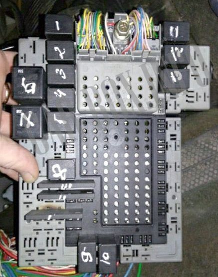
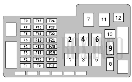
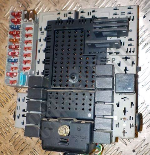
In the engine compartment
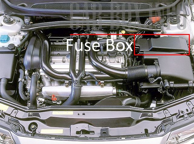
It is located near the left shock absorber post. The unit has several versions. To access it, remove the cover by pressing the two latches.
Access example.
Type 1
vin 116811
| Diagram | ||
|---|---|---|
|
||
| No. | Description | A |
| F1 | Additional heater | 25 |
| F2 | Extra equipment | 15 |
| F3 | - | |
| F4 | Heated oxygen sensors | 20 |
| F5 | Engine management system (petrol) | 15 |
| F6 | Engine management | 15 |
| F7 | Throttle valve control unit | 10 |
| F8 | Accelerator pedal position sensor, air conditioning | 10 |
| F9 | Horn (beep) | 15 |
| F10 | Rear window washer pump relay | 10 |
| F11 | Engine Management, Glow Plugs, Air Conditioning, Coolant Heater (Diesel), Crankcase Ventilation Heater | 20 |
| F12 | Stop lights | 5 |
| F13 | Windshield wiper | 25 |
| F14 | Anti-lock brakes / dynamic stability control and traction control system | 30 |
| F15 | - | |
| F16 | Headlight washer / wiper system, windshield washer pump relay | 15 |
| F17 | Headlights - dipped beam ( S80 ^ 04/00, V70VIN ^ 026212, V70XC VI N ^ 001099 ) | 15 |
| F18 | Headlights - high beam ( S80 ^ 04/00, V70 VIN ^ 026212, V70XC VI N ^ 001099 ) | 20 |
| F19 | Anti-lock brakes / dynamic stability control and traction control system | 30 |
| F20 | Coolant Heater Relay 2 - Diesel | 30 |
| F21 | Coolant Heater Relay 1 - Diesel | 30 |
| F22 | Starter relay | 25 |
| F23 | Engine control relay, electronic engine control module (ECM) | 5 |
| F24 | - | |
| 1 | Coolant Heater Relay 1 (Diesel) | |
| 2 | Engine control relay | |
| 3 | Glow plug relay | |
| 4 | Starter relay | |
| 5 | Windshield wiper intermittent operation relay | |
| 6 | Relay of Bi-fuel two-part fuel supply system | |
| 7 | Coolant Heater Relay 2 (Diesel) | |
| 8 | Air conditioner compressor solenoid clutch relay | |
| 9 | Horn relay | |
| 10 | Windshield washer pump relay | |
| 11 | Windshield wiper motor relay | |
| 12 | Rear window washer pump relay | |
Type 2
vin 116810
| Diagram | ||
|---|---|---|
|
||
| No. | Description | A |
| F1 | Glow plugs | 60 |
| F2 | Interior fuse box (F32-38), front / rear marker lamp relay | 60 |
| F3 | F9-10, passenger compartment fuse box (F3-6 and F16-19), ignition main circuit relay, ignition auxiliary circuit relay 2 | 60 |
| F4 | F11-13 fuse box / relay-instrument cluster 1 (F20-28) | 60 |
| F5 | Not used | - |
| F6 | - | |
| F7 | F17-18 Cooling fan motor control unit | 60 |
| F8 | Not used | - |
| F9 | High beam relay | 20 |
| F10 | Headlamp dipped beam relay | 15 |
| F11 | Stop lights | 5 |
| F12 | Windshield wiper | 25 |
| F13 | Headlamp Washer / Wiper System, Windshield Washer Pump Relay | 15 |
| F14 | Not used | - |
| F15 | - | |
| F16 | Horn (beep) | 15 |
| F17 | Additional heater | 25 |
| F18 | Extra equipment | 25 |
| F19 | Anti-lock braking system (ABS) | 30 |
| F20 | 30 | |
| F21 | Starter | 25 |
| F22 | Electronic Engine Control Module (ECM) Engine Control Relay | 5 |
| F23 | Empty | - |
| F24 | Accelerator pedal position sensor, gearbox ECU, air conditioning | 20 |
| F25 | Engine Management, Glow Plugs, Air Conditioning, Coolant Heater (Diesel), Crankcase Ventilation Heater (Diesel) | 20 |
| F26 | Engine management | 15 |
| F27 | Heated oxygen sensors | 20 |
| F28 | Engine management system, crankcase ventilation heater (Diesel) | 15 |
| F29 | Throttle valve control unit | 10 |
| 1 | A / C compressor electromagnetic clutch relay | |
| 4 | Horn relay | |
| 5 | Windshield wiper motor relay | |
| 8 | Windshield wiper intermittent operation relay | |
| 9 | Coolant Heater Relay 1 (Diesel) | |
| 10 | ||
| 11 | Windshield washer pump relay | |
| 16 | Glow plug relay | |
| 19 | Engine control relay | |
| 23 | Starter relay | |
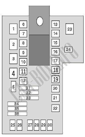
In the trunk
There are two distribution boxes here that are responsible for protecting the electrical circuits.
Fuse box

It is located behind the trim on the left side. To access it, turn the handle (1) 90 degrees and bend the trim downwards.
General view of the Volvo S80 trunk fuse box.
| Diagram | ||
|---|---|---|

|
||
| No. | Description | A |
| F1 | Multifunction control unit 2, interior trunk illumination | 10 |
| F2 | Rear fog lights | 10 |
| F3 | Stop lights | 15 |
| F4 | Back-up lights | 10 |
| F5 | not used | |
| F6 | Trunk lid/rear door lock | 10 |
| F7 | Rear seat head restraints, power connector for optional equipment in the luggage compartment | 10/15 |
| F8 | Central locking - rear doors, fuel filler flap/cover | 15 |
| F9 | Trailer electrical connector | 20 |
| F10 | Audio system, navigation system | 10 |
| F11 | Extra equipment | 15 |
| F12 | not used | |
| F13 | not used | |
| F14 | not used | |
| F15 | not used | |
| F16 | not used | |
| F17 | not used | |
| F18 | not used | |
| 4 | Rear window wiper motor (V70) | |
| 7 | Trunk lid / rear door opener actuator relay | |
| 8 | Trunk lid / rear door opening actuator relay, trunk lid/rear door lock actuator relay | |
| 9 | Fuel filler flap lock actuator relay - opening | |
| 10 | Fuel filler flap / fuel filler flap actuator relay - closing | |
| 11 | Rear Right Door Central Locking Relay - Unlock | |
| 12 | Rear Right Door Central Locking Relay - Locking | |
| 13 | Rear head restraint actuator relay | |
| 14 | Rear wiper motor relay (V70) | |
| 19 | Jumper - brake lights | |
| 20 | Jumper - rear position lamps | |
| 21 | ||
| 22 | Jumper - auxiliary equipment power connector in the luggage compartment | |
| 23 | Jumper - fog lights | |
| 25 | Rear Fog Lamp Relay - Trailer | |
| 26 | Rear fog lamp relay | |
| 27 | Brake light relay | |
| 28 | Back-up lamps relay | |
| 29 | Central locking relay, rear doors - double interlocking | |
| 30 | Left Rear Door Central Locking Relay - Unlocking | |
| 31 | Left rear door central locking relay - blocking | |
| 34 | Rear window heater relay | |
| 36 | Trailer connector power relay | |
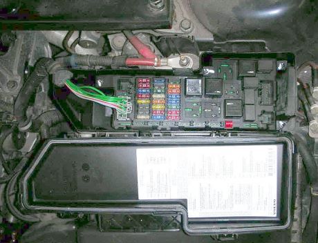
Power box
Located near the battery.
| Diagram | ||
|---|---|---|

|
||
| No. | Description (models up to 04.2000) | A |
| F1 | Reserve | - |
| F2 | Reserve | - |
| F3 | Reserve | - |
| F4 | Reserve | - |
| F5 | Rear window heater | 40 |
| F6 | Luggage compartment fuse box (F6-10) / (F1-5) | 40 |
| F7 | 40 | |
| No. | Description (models from 04.2000 onwards) | A |
| F1 | Trailer connector power relay | 40 |
| F2 | Luggage compartment fuse box (F12-14) | 40 |
| F3 | Rear window heater | 40 |
| F4 | Reserve | - |
| F5 | Trunk fuse box (F6-10) | 40 |
| F6 | Reserve | - |
| F7 | Trunk fuse box (F1-5) | 40 |
