
The third generation of the Volvo XC70 / V70 estate/station wagon was introduced in 2007. The XC variant was engineered for travel and all-terrain capability, featuring increased ground clearance, body protection, larger wheels, and all-wheel drive. This article provides comprehensive fuse box diagrams and location guides for the Volvo XC70 and V70 (chassis codes 135 / 136; P3 platform) for model years 2007, 2008, 2009, 2010, 2011, 2012, 2013, 2014, 2015, and 2016.

Below you will find fuse box locations, photos, and circuit assignments. Fuses for the “Cigarette lighter” and “Fuel pump” are highlighted in bold.
Passenger Compartment Fuse Box
Depending on the vehicle model year, the passenger compartment contains either one or two fuse panels.
Primary Fuse Box
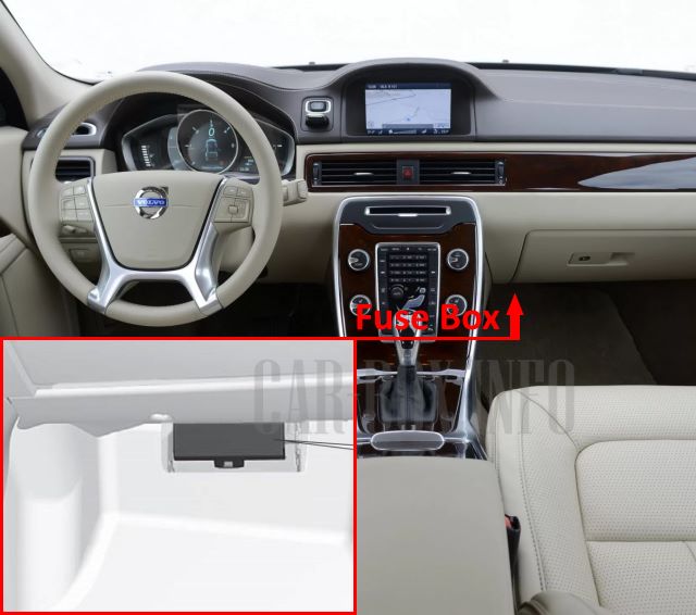
Located under the glove compartment on the passenger side.
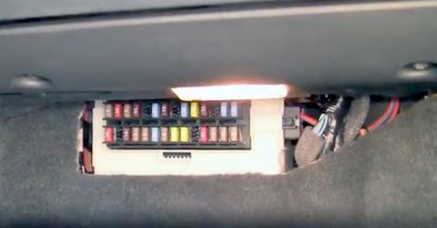
To access the distribution box, fold back the interior trim panel covering the unit and press the catch to swing the protective cover upward.
| Diagram | ||
|---|---|---|
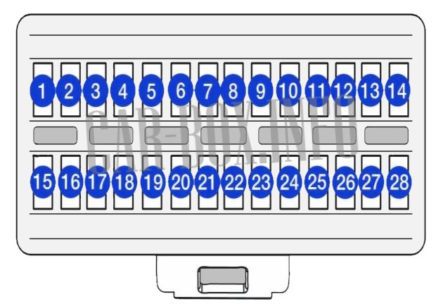 |
||
| No. | Description | A |
| F1 | Rain sensor | 5 |
| F2 | SRS airbag system module | 10 |
| F3 | ABS system module | 5 |
| F4 | Accelerator pedal sensor, auxiliary cabin heater (PTC)*, heated seats | 7.5 |
| F5 | Spare | |
| F6 | ICM display, CD player and Radio module, RSE system | 15 |
| F7 | Multifunction steering wheel controls module | 7.5 |
| F8 | Spare | |
| F9 | Headlamps | 15 |
| F10 | Power sunroof | 20 |
| F11 | Reversing lights | 7.5 |
| F12 | Spare | |
| F13 | Front fog lights | 15 |
| F14 | Windshield wiper / washer system | 15 |
| F15 | Cruise control system | 10 |
| F16 | Spare | |
| F17 | Interior lighting, driver's door control panel, power passenger seat | 7.5 |
| F18 | Instrument cluster module | 5 |
| F19 | Power driver's seat module | 5 |
| F20 | Spare | |
| F21 | Immobilizer / Anti-theft alarm system | 5 |
| F22 | Fuel module (Volvo XC70 / V70 fuel pump fuse) | 20 |
| F23 | Steering column lock module | 20 |
| F24 | Spare | |
| F25 | Fuel filler flap / tailgate lock mechanism | 10 |
| F26 | Alarm siren, ECC (Electronic Climate Control) | 5 |
| F27 | Starter / Ignition system | 5 |
| F28 | Brake lights | 5 |
Secondary Fuse Block
Located adjacent to the primary block. Installed only on Volvo XC70 / V70 models from the 2011–2016 model years.
| Diagram | ||
|---|---|---|
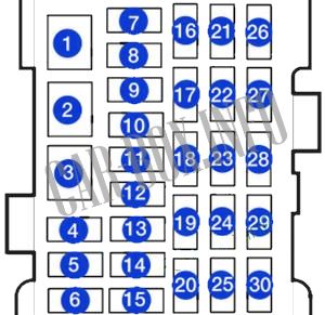 |
||
| No. | A | Circuit Assignment |
| 1 | 40 | Main fuse, audio system amplifier; subwoofer |
| 2 | - | Spare |
| 3 | - | Spare |
| 4 | - | Spare |
| 5 | - | Spare |
| 6 | - | Spare |
| 7 | 15 | 12V power outlet in cargo area |
| 8 | 20 | Driver door control module |
| 9 | 20 | Front passenger door control module |
| 10 | 20 | Rear right door control module |
| 11 | 20 | Rear left door control module |
| 12 | 20 | Keyless entry receiver module (if equipped) |
| 13 | 20 | Power driver's seat (if equipped) |
| 14 | 20 | Power passenger seat (if equipped) |
| 15 | 15 | Folding rear headrests (if equipped) |
| 16 | - | Spare |
| 17 | 10 | Radio, display screen, RTI navigation system (if equipped) |
| 18 | 15 | Infotainment control module |
| 19 | 5 | Bluetooth / Phone module (if equipped) |
| 20 | - | Spare |
| 21 | 5 | Power sunroof (if equipped), interior lighting, cabin climate sensor |
| 22 | 15 | Rear console 12V socket / cigarette lighter; RSE system (if equipped) |
| 23 | 15 | Heated front passenger seat |
| 24 | 15 | Heated driver's seat |
| 25 | - | Spare |
| 26 | 15 | Heated rear right seat (if equipped) |
| 27 | 15 | Heated rear left seat (if equipped) |
| 28 | 5 | Park Assist, parking camera, RTI navigation system (if equipped) |
| 29 | 10 | All-Wheel Drive (AWD) control module (if equipped) |
| 30 | 10 | Four-C active chassis system (if equipped) |
Cargo Area Fuse Box
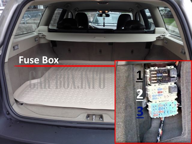
Located on the left side of the cargo area behind the interior side panel. It consists of three interconnected module boards (black, white, and blue).
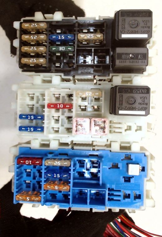
General view of the Volvo XC70 / V70 cargo area fuse box.
| Diagram | ||
|---|---|---|
| No. | Description | A |
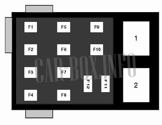
| Panel #1 (Black) | ||
 |
||
| F1 | Front left door control module | 25 |
| F2 | Front right door control module | 25 |
| F3 | Rear left door control module | 25 |
| F4 | Rear right door control module | 25 |
| F5 | Spare | - |
| F6 | 12V accessory socket in cargo area, cooler box | 15 |
| F7 | Heated rear window | 30 |
| F8 | Spare | - |
| F9 | Trailer hitch electrical socket | 15 |
| F10 | Power driver's seat | 25 |
| F11 | Trailer control module | 40 |
| F12 | Power tailgate drive control module | 30 |
| 1 | Rear window wiper relay | - |
| 2 | Heated rear window relay | - |
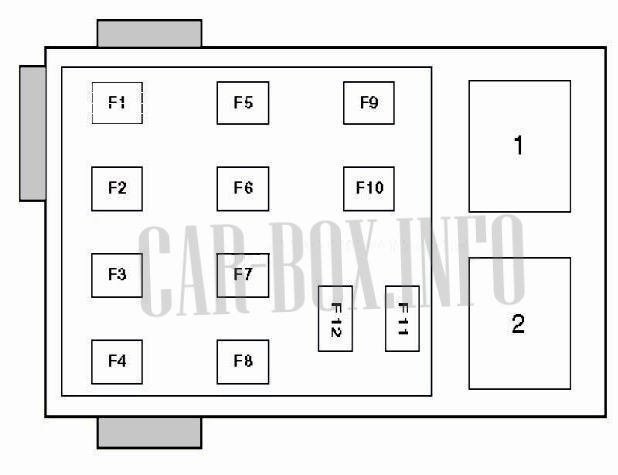
| Panel #2 (White) | ||
 |
||
| F1 | Spare | - |
| F2 | Active suspension control module (Four-C) | 15 |
| F3 | Heated driver's seat | 15 |
| F4 | Heated front passenger seat | 15 |
| F5 | Heated rear right seat | 15 |
| F6 | All-Wheel Drive (AWD) control module | 10 |
| F7 | Heated rear left seat | 15 |
| F8 | Spare | - |
| F9 | Power passenger seat | 25 |
| F10 | Keyless entry system receiver module | 20 |
| F11 | Electric parking brake, left actuator | 30 |
| F12 | Electric parking brake, right actuator | 30 |
| 1 | Power rear headrest fold relay | - |
| 2 | Main ignition circuits relay | - |
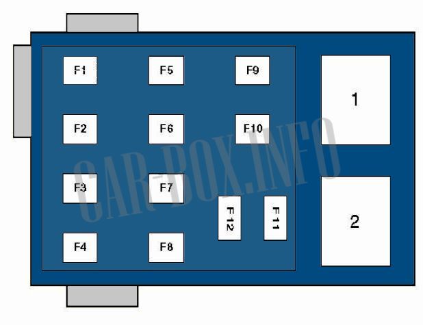
| Panel #3 (Blue) | ||
 |
||
| F1 | Infotainment display screen | 10 |
| F2 | Spare | - |
| F3 | Audio subwoofer | 25 |
| F4 | Spare | - |
| F5 | Audio control module | 25 |
| F6 | 15 | |
| F7 | Cellular phone module | 5 |
| F8 | Spare | - |
| F9 | Spare | - |
| F10 | Spare | - |
| F11 | Spare | - |
| F12 | Spare | - |
Engine Compartment Fuse Box
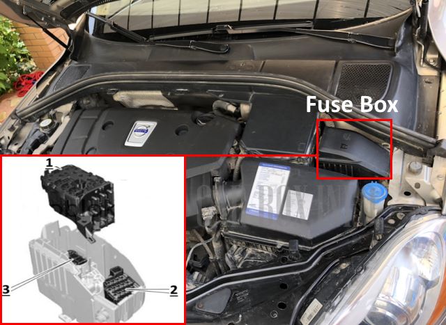
The underhood fuse box is located beneath the protective plastic cover near the windshield washer reservoir. It consists of three distinct sections.
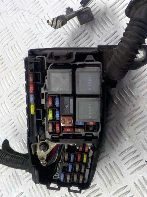
Representative layout example.
| Diagram | ||
|---|---|---|
| No. | Description | A |
| Section #1 | ||
 |
||
| F1 | Central Electronic Module (CEM) / Power distribution | 50 |
| F2 | 50 | |
| F3 | 60 | |
| F4 | 60 | |
| F5 | 50 | |
| F6 | Spare | - |
| F7 | Auxiliary cabin heater (PTC) | 100 |
| F30 | Engine Control Module (ECM) | 10 |
| F31 | Transmission Control Module (TCM) | 15 |
| F32 | A/C compressor clutch / Climate control | 15 |
| F33 | Windshield washer relay | 5 |
| F34 | Starter motor relay | 30 |
| F35 | Engine Control Module (ECM) | 20 |
| 10 | ||
| F36 | Engine Control Module (ECM) | 15 |
| 10 | ||
| F37 | Engine Control Module (ECM) | 15 |
| F38 | Engine solenoids and valves | 10 |
| F39 | Engine Control Module (ECM) | 15 |
| 10 | ||
| F40 | Positive crankcase ventilation (PCV) heater (5-cylinder petrol engine) | 20 |
| F41 | Engine Control Module (ECM) | 5 |
| F42 | Glow plug control module (Diesel) | 70 |
| F43 | Spare | - |
| F44 | Engine cooling fan module | 80 |
| 60 | ||
| 10 | Spare | - |
| 11 | Spare | - |
| 12 | Starter relay | - |
| 13 | A/C compressor clutch relay | - |
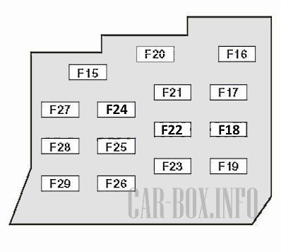
| Section #2 | ||
 |
||
| F15 | Spare | - |
| F16 | Headlamps | 10 |
| F17 | Central Electronic Module (CEM) | 20 |
| F18 | Adaptive cruise control radar sensor | 5 |
| F19 | Speed-dependent power steering module | 5 |
| F20 | Engine Control Module (ECM), SRS restraint control module | 10 |
| F21 | Heated windshield washer nozzles | 10 |
| F22 | Brake vacuum pump | 20 |
| F23 | Headlamp switch module | 5 |
| F24 | Headlamp washer pump | 15 |
| F25 | Volvo XC70 / V70 12V power sockets (front and rear console) / cigarette lighter fuse | 15 |
| F26 | Power sunroof (if equipped), overhead console / ECC climate control | 10 |
| F27 | Central Electronic Module (CEM) relay | 5 |
| F28 | Auxiliary driving lights / Spotlamps | 20 |
| F29 | Horn | 15 |
| Section #3 | ||
 |
||
| F8 | Spare | - |
| F9 | Windshield wiper motor / washer system | 30 |
| F10 | Fuel-fired auxiliary heater control module | 20 |
| F11 | HVAC blower motor / heater fan | 40 |
| F12 | Spare | - |
| F13 | ABS / ESC control module | 40 |
| F14 | 20 | |
| 8 | Main ignition circuits relay | - |
| 9 | Central Electronic Module (CEM) relay | - |

good info