This material discusses in detail the fuse diagrams of Chery cars: Bonus and Very (first generation / A13 index): 2008, 2009, 2010, 2011, 2012, 2013, 2014, 2015, 2016, 2017, 2018, 2019 of release.

Fuse number 16 in the passenger compartment is responsible for protecting the cigarette lighter.
In the engine compartment

There are two distribution boxes here, which are responsible for protecting the vehicle's electrical circuits.
Power fuse links
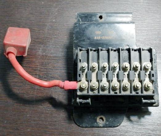
The panel is marked with the number 1. It is located on the positive terminal of the battery. Consists of high power fuses.
| Diagram | |
|---|---|
|
|
| No. | Description |
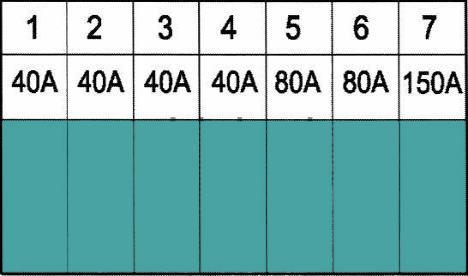
| 1 | cooling fan 40A |
| 2 | anti-lock brake system 40A |
| 3 | |
| 4 | fuse box in the cabin 40A |
| 5 | body control unit 80A |
| 6 | starter 80A |
| 7 | generator 150A |
Relay box
Marked with number 2.
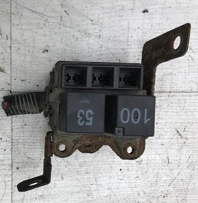
General view.
| Diagram | |
|---|---|
|
|
| No. | Description |
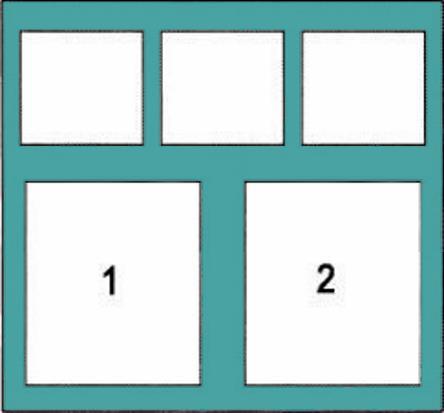
| 1 | cooling fan relay (high speed) |
| 2 | cooling fan relay (low speed) |
In the cabin
There are also two blocks responsible for protecting the electrical circuits of the car.
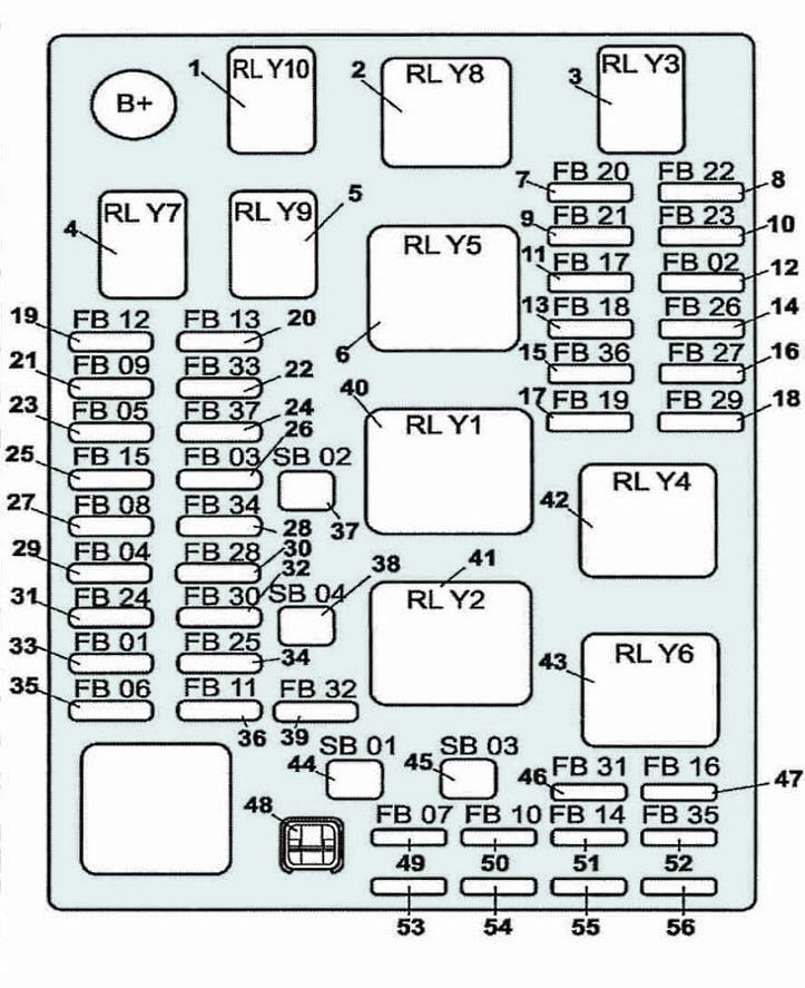
Main distribution unit
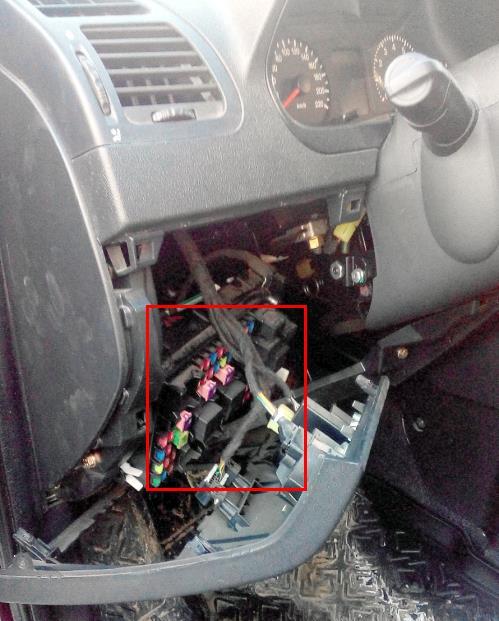
The main fuse and relay box is located behind the dashboard trim on the driver's side.
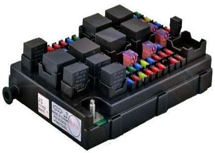
General view.
| Diagram | ||
|---|---|---|
|
||
| No. | Description | Amps |
| 1/RLY10 | low beam relay | - |
| 2 / RLY 8 | main relay | - |
| 3 / RLY3 | high beam relay | - |
| 4/RLY7 | fuel pump relay | - |
| 5/RLY9 | air conditioner compressor relay | - |
| 6/RLY5 | spare relay | - |
| 7/FB20 | high beam lamps - left headlight | 10 |
| 8/FB22 | dipped beam lamps - left headlight | 10 |
| 9/FB21 | high beam lamps - right headlight | 10 |
| 10/FB23 | dipped beam lamps - right headlight | 10 |
| 11/FB17 | fan | 15 |
| 12/FB02 | audio system | 10 |
| 13/FB18 | oxygen sensor | 10 |
| 14/FB26 | door mirror adjuster | 10 |
| 15/FB36 | ignition module | 15 |
| 16/FB27 | cigarette lighter fuse Chery Bonus / Very | 15 |
| 17/FB19 | engine control unit, injectors | 15 |
| 18/FB29 | spare | 30 |
| 19/FB12 | fuel pump fuse | 15 |
| 20/FB13 | air conditioning compressor | 15 |
| 21/FB09 | instrument cluster | 10 |
| 22/FB33 | spare | 30 |
| 23/FB05 | sunroof module | 20 |
| 24/FB37 | spare | 30 |
| 25/FB15 | engine control unit | 10 |
| 26/FB03 | audio system | 15 |
| 27/FB08 | open door indicator lamps | 10 |
| 28/FB34 | spare | 20 |
| 29/FB04 | alarm control unit | 10 |
| 30/FB28 | spare | 15 |
| 31/FB24 | airbags | 15 |
| 32/FB30 | reversing lamps | 10 |
| 33/FB01 | air conditioner | 10 |
| 34/FB25 | ABS | 10 |
| 35/FB06 | tire pressure monitoring system | 7.5 |
| 36/FB11 | speed sensor | 10 |
| 37/SB02 | starter | 30 |
| 38/SB04 | air conditioner | 30 |
| 39/FB32 | stop lamps | 15 |
| 40/RLY1 | starter relay | - |
| 41/RLY2 | air conditioning relay | - |
| 42/RLY4 | spare | - |
| 43/RLY6 | spare | - |
| 44/SB01 | ignition switch | 30 |
| 45/SB03 | spare | 30 |
| 46/FB31 | spare | 7.5 |
| 47/FB16 | spare | 7.5 |
| 48 | tweezers | - |
| 49/FB07 | instrument cluster | 10 |
| 50/FB10 | diagnostic systems | 10 |
| 51/FB14 | the engine control unit | 10 |
| 52/FB35 | spare | 15 |
| 53 | spare | 10 |
| 54 | spare | 15 |
| 55 | spare | 20 |
| 56 | spare | 30 |
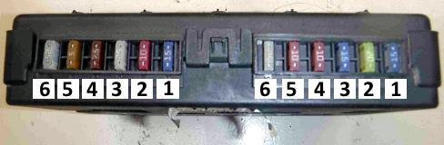
Additional distribution box

Behind the main unit is another fuse box.
| Diagram | ||
|---|---|---|
|
||
| No. | Description | Amps |
| Left-hand side | ||
| 1 | central locking | 15 |
| 2 | Rear fog lamps | 10 |
| 3 | Power windows rear side doors | 25 |
| 4 | Luggage compartment ceiling lamps and illumination of the opening of the right front door, right side light | 7.5 |
| 5 | A lamp of a plafond of illumination of an aperture of the left forward door, the left dimensional light | 5 |
| 6 | Front electric windows | 25 |
| Right side | ||
| 1 | Hazard lamps | 15 |
| 2 | Rear window heater | 20 |
| 3 | Fog lamps | 15 |
| 4 | Horns | 10 |
| 5 | Interior lamp | 10 |
| 6 | windshield wiper | 25 |
