In this article, we will take a detailed look at the fuse diagrams for the DR Motor DR5 / Chery Tiggo T11 car (first generation, including FL restyling): 2005, 2006, 2007, 2008, 2009, 2010, 2011, 2012, 2013, 2014, 2015, 2016 release. Also known as Speranza Tiggo, Chery J11, Matchedje V3.

Fuse #5 in the passenger compartment primary block is responsible for the cigarette lighter socket.
In the engine compartment
There are two distribution boxes here, which are responsible for protecting the vehicle's electrical circuits.
Fuse box
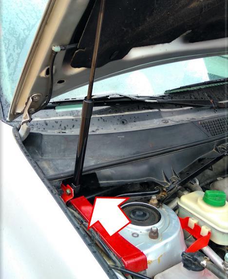
It is located near the right front shock absorber strut.
To access:
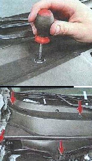
1 - unscrew the screws securing the block cover.
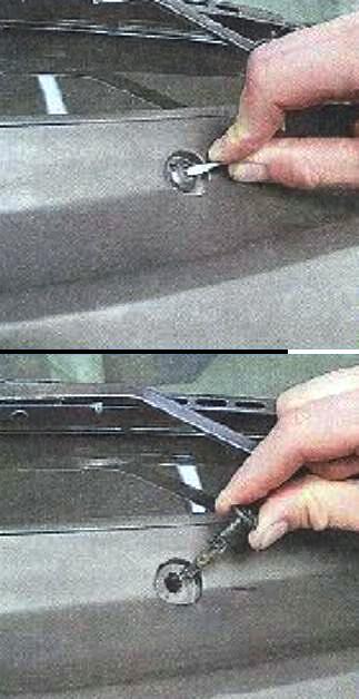
2 - Push in the lock core and pull it out of the hole.
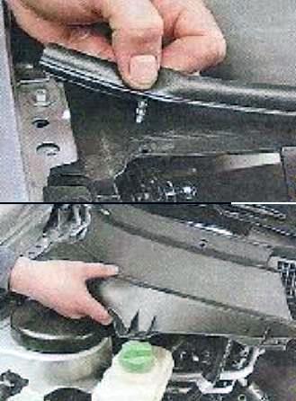
3 - disconnect the rubber seal of the air intake box from the block cover.
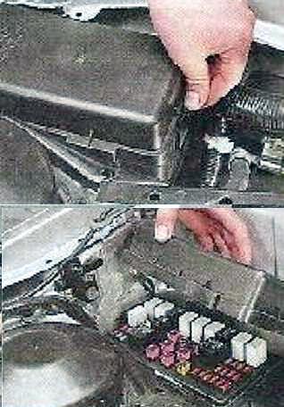
4 - having pressed the latch, remove the cover of the distribution box.
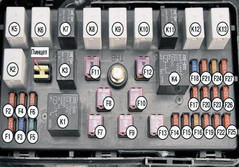
| Diagram | ||
|---|---|---|
|
||
| No. | Description | Amps |
| K1 | Heater fan relay (cabin ventilation) | |
| K2 | Gasoline pump relay (fuel pump) for cars with a 1.6 liter engine. and 2.0 l); | |
| Spare relay (for vehicles with 1.8L engine) | ||
| K3 | Auxiliary Radiator Fan Low Speed Relay (#3) | |
| K4 | T11: Starter relay | |
| T11 facelift (FL): Main relay | ||
| K5 | Relay low beam headlights | |
| K6 | High Beam Relay | |
| K7 | Main Radiator Fan High Speed Relay (#2) | |
| K8 | Spare relay (for vehicles with 1.6 l and 2.0 l engines); TCU pump relay (for vehicles with 1.8L engine) | |
| K9 | T11: Front fog lamp relay (front PTF); | |
| T11 restyling (FL): Reserve | ||
| K10 | T11: Relay for rear fog lights (rear PTF); | |
| T11 restyling (FL): Reserve | ||
| K11 | Radiator Fan Switch Relay (#1) | |
| K12 | T11: Relay for increasing the speed of the motors of the engine cooling system (radiator); | |
| T11 restyling (FL): Reserve | ||
| K13 | Spare | |
| F1 | Dipped beam - left headlight | 10 |
| F2 | Dipped beam - right headlight | 10 |
| F3 |
|
15 |
| F4 | High beam - left headlight | 10 |
| F5 | Furnace fan (cabin fan) | 30 |
| F6 | High beam - right headlight | 10 |
| F7 | Radiator and A/C auxiliary fan low speed #2 | 30 |
| F8 | 30 | |
| F9 | T11: Reserve; | 30 |
| T11 facelift (FL): Main connection fuse (for vehicles with 1.6L and 2.0L engines); TCU pump (for vehicles with 1.8L engine) | 30 | |
| F10 | Spare | 30 |
| F11 | T11: Spare; | 30 |
| T11 restyling (FL): Starter | 30 | |
| F12 | T11: Starter (relay contacts); | 30 |
| T11 facelift (FL): Main relay fuse | 30 | |
| F13 | Door lock and alarm control unit (ISU fuse) | 60 |
| F14 | reversing lamp | 10 |
| F15 | T11: Ignition unit; | 10/15 |
| T11 restyling (FL): Spare fuse (for vehicles with 1.6L and 2.0L engines), TCU power circuit fuse (for vehicles with 1.8L engines) | 10/15 | |
| F16 | Generator | 5 |
| F17 | Position lamps - right side of the vehicle | 10 |
| F18 | T11: Fog lights (front); | 15 |
| T11 restyling (FL): Spare | 15 | |
| F19 | Switching the windings of the radiator fan (engine cooling system) and air conditioning (relay No. 1,2,3) | 10 |
| F20 | Side Lamps - Left Side of Vehicle | 10 |
| F21 | T11: Rear fog lights; | 10 |
| T11 facelift (FL): Spare fuse | 10 | |
| F22 | T11: Spare; | 10 |
| T11 restyling (FL): Engine management system | 10 | |
| F23 | Stop lights | 10 |
| F24 | T11: Starter relay coil; | 5 |
| T11 restyled (FL): Main relay coil | 5 | |
| F25 | T11: A/C Compressor Clutch (A/C A/C); | 10 |
| T11 facelift (FL): Oxygen sensor | 10 | |
| F26 | T11: ABS controller (ABS); | 10 |
| T11 facelift (FL): Ignition coils | 10 | |
| F27 | Engine control unit (ECU) (ECU) | - |
Power fuse links
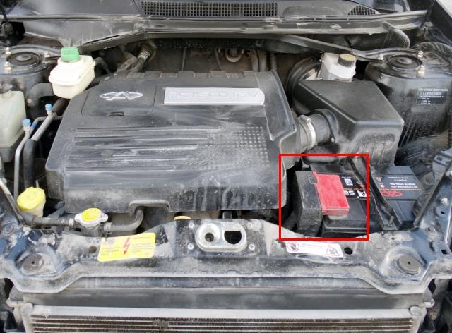
The high power fuse panel is located on the *+* terminal of the battery.
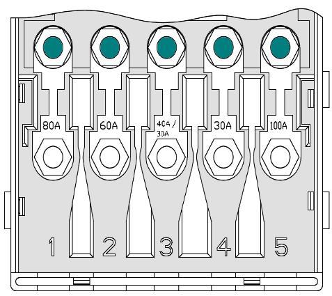
| Diagram | ||
|---|---|---|
|
||
| No. | Description | Amps |
| 1 | To the front compartment of the electrical distribution block, terminal E | 80 |
| 2 | To the front compartment of the electrical distribution block, terminal D | 60 |
| 3 | T11: 30A - power supply and drive of the ABS module T11 restyling (FL): 40A - power supply and drive of the ABS module |
30/40 |
| 4 | ABS module (power supply, valve) | 30 |
| 5 | Cabin fuse box (power supply), terminal C | 100 |
In the passenger compartment
In the cabin space there are two blocks responsible for protecting the electrical circuits of the car.
Primary fuse box
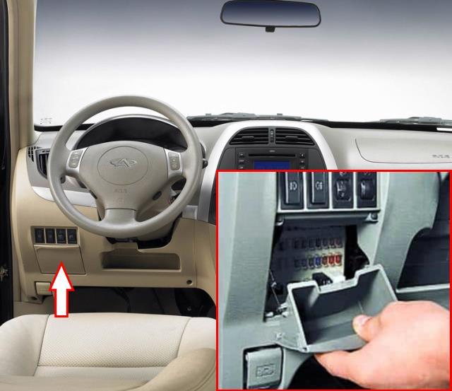
Located on the driver's side. To access it, you need to remove the glove box. Open the glove compartment, pull it up and remove it by disconnecting the spring.
| Diagram | ||
|---|---|---|

|
||
| No. | Description | Amps |
| K1 | A/C/Cooling Fan 4th Speed Relay | |
| K2 |
|
|
| K3 | T11 facelift (FL): A/C compressor relay | |
| K4 | Reserve | |
| K5 | Horn relay | |
| K6 |
|
|
| K7 |
|
|
| F1 | Adjusting the brightness of instrument lighting | 5 |
| F2 | T11: Oxygen sensor (lamda probe), gas tank valve, speedometer; | 10 |
| T11 facelift (FL): Brake pedal sensor fuse, vehicle speed sensor | 10 | |
| F3 | T11: Injectors; | 10 |
| T11 facelift (FL): ABS brake control unit (ABS) | 10 | |
| F4 | A/C switch, on/off button. | 5 |
| F5 | Tiggo cigarette lighter fuse | 15 |
| F6 | Dashboard | 10 |
| F7 | Radio tape recorder (audio system) | 15 |
| F8 | Connector for OBD diagnostics | 10 |
| F9 | Dashboard | 10 |
| F10 | Rear wiper (wiper) and washer | 15 |
| F11 | Windshield wiper (wipers) and windshield/windshield washer | 25 |
| F12 | Relay Coil Fuse (High and Low Beam) | 5 |
| F13 | Airbags | 10 |
| F14 | Radio: audio control system | 5 |
| F15 | Side mirror adjustment | 7.5 |
| F16 | Heated / heated front seats | 15 |
| F17 | Engine control unit (ECU) | 10 |
| F18 | T11: Lock control unit and alarm module; | 10 |
| T11 facelift (FL): ISU power circuits (BCM) | 10 | |
| F19 | T11: Power windows; | 20 |
| T11 facelift (FL): A/C compressor fuse | 20 | |
| F20 | Sunroof (electric) | 20 |
| F21 | Ignition key presence sensor | 15 |
| F22 | T11: Interior lights, door backlight, door open sensor; | 15 |
T11 restyling (FL):
|
15 | |
| F23 | Sunroof (sunroof control) | 5 |
| F24 | Sound signal (beep, klaxon) | 15 |
| F25 | Management of modes of supply and recirculation of air in the cabin | 10 |
| F26 | T11: On the air conditioner relay (winding); | 10 |
| T11 FL: Anti-theft fuse | 10 | |
| F27 | Heated / heated side mirrors | 10 |
| F28 | Slow blowing fuse AM2 (through the ignition switch goes to the lines IG1 and ACC) | 40 |
| F29 | Slow blowing fuse AM1 (through the ignition switch goes to the IG2 line and the starter relay winding) | 40 |
| F30 | T11: Reserve; | 15 |
| T11 FL: Passenger side accessory socket | 15 | |
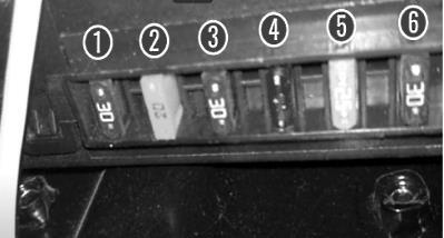
Additional block (ISU)
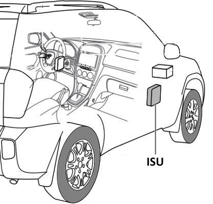
Placed under the passenger glove box.
| Diagram | ||
|---|---|---|
|
||
| No. | Description | Amps |
| 1 | Front power windows | 30 |
| 2 | Anti-theft alarm (siren, lock) | 20 |
| 3 | Rear power windows | 30 |
| 4 | Daytime running lights, direction indicators, energy-saving battery | 15 |
| 5 | central locking | 20/25 |
| 6 | Rear window heating | 30 |
