In this article, we will take a detailed look at the fuse diagrams for the Chery Tiggo car (first generation): 2017, 2018, 2019, 2020, 2021, 2022, 2023 of release.

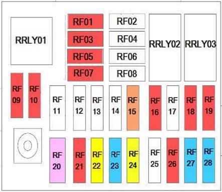
Fuses number RF27 and RF28 in the cabin block are responsible for the cigarette lighter sockets.
In the passenger compartment
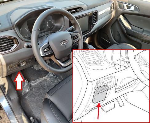
The distribution box is located on the driver's side, behind the dashboard trim. To access:

1. Remove the end cap.

2. Turn off two fixing screws and remove facing.
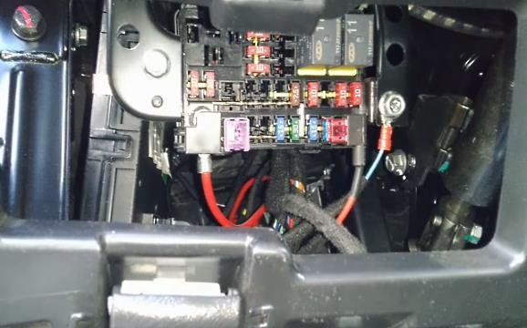
Access example.
| Diagram | ||
|---|---|---|
|
||
| No. | Description | Amps |
| RRLY 01 | Backup relay | |
| RRLY 02 | Reversing lamp for ISS | |
| RRLY 03 | Heated rear window relay | |
| RF01 | Comfort Unit, Dashboard/Instrument Cluster Control Unit, Immobilizer (BCM & ICM & IMMO) | 10 |
| RF02 | Not involved | |
| RF03 | Steering wheel angle sensor, EPS (EPS & SAM) | 10 |
| RF04 | Not available or on some trims -360 Surround Vision System, Blind Spot Detection System, Multimedia System, Vehicle Proximity Warning Radar (AVM & BSD & MPC & MRR) | 10 |
| RF05 | Airbags, system control unit (AIR BAG) | 10 |
| RF06 | Not involved | - |
| RF07 | A/C Control Panel, Head Unit Control Panel, Headlight Leveling Switch Power, Sunroof Control Switch (SEE NOTE) | 10 |
| RF08 | Not involved | - |
| RF09 | Radio, head unit control unit, air conditioning and heater control panel (RADIO & AC & T-BOX) | 10 |
| RF10 | Front panel control unit, rain sensor (ICM & Rain Sensor) | 10 |
| RF11 | Not involved | - |
| RF12 | Not involved | - |
| RF13 | Not involved | - |
| RF14 | Not involved | |
| RF15 | Diagnostics, Tracker Unit, Key in Signal Position, Remote Control Mode, Heating Relay Coil (DIAGNOSIS & VTM & KEYIN & EPB SW) | 7.5 |
| RF16 | USB charging unit, usb port | 10 |
| RF17 | Not involved | - |
| RF18 | Heated side mirrors with electric adjustment (left and right), Feedback of the operation of the rear window heating / heating system (MIRROR HEATER) | 10 |
| RF19 | PEPS keyless entry and start system, 4WD system, ECU and DC-DC (ISS) start-stop system (PEPS&DC(ISS)) | 10 |
| RF20 | Seat adjustment, power seats (SEAT ADJ) | 30 |
| RF21 | AM2 circuit when starting the engine (on a car without a PEPS keyless entry system) (IGN SW2) | 10 |
| RF22 | Not engaged or ignition position 1 (IGN SW1) | 20 |
| RF23 | reversing lights | 10/15 |
| RF24 | Heated rear window, relay 03 | 30 |
| RF25 | Not involved | - |
| RF26 | Head unit control unit, left and right mirror adjustment actuator, BCM unit, sunroof (RADIO & BCM & MIRROR ADJ & SUN) | 10 |
| RF27 | Cigarette lighter fuse Chery Tiggo T4 | 15 |
| RF28 | Cigarette Lighter / Power Outlet (SPARE POWER) | 15 |
In the engine compartment
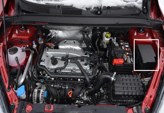
There are two distribution boxes here, which are responsible for protecting the vehicle's electrical circuits.
Power fuses
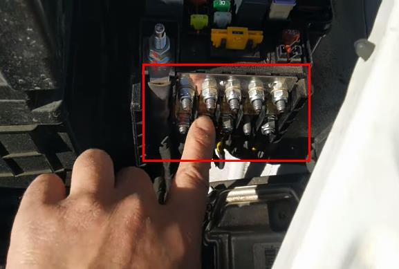
Located at the end of the main unit.
| Diagram | ||
|---|---|---|

|
||
| No. | Purpose | Amps |
| 1 | Generator | 150 |
| 2 | Cooling fan low speed | 40 |
| 3 | High speed radiator fan | 50 |
| 4 | Electric Power Steering (EPS) | 80 |
| 5 | Fuse box in the cabin | 60 |
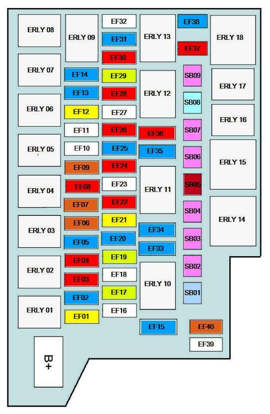
Fuse box
Located near the battery.
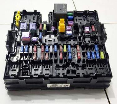
General view.
| Diagram | ||
|---|---|---|
|
||
| No. | Description | Amps |
| ERLY 01 | Auxiliary (ACC) | |
| ERLY 02 | High Beam Relay (HIGH BEAM) | |
| ERLY 03 | Ignition (IGN) | |
| ERLY 04 | Low Beam Relay (LOW BEAM) | |
| ERLY 05 | Engine Management System (EMS) | |
| ERLY 06 | Vacuum pump | |
| ERLY 07 | reversing lights | |
| ERLY 08 | Low speed wiper blades | |
| ERLY 09 | High Speed Wiper | |
| ERLY 10 | Transmission control unit (TCU) relay | |
| ERLY 11 | HORN | |
| ERLY 12 | Air Conditioning Compressor Electromagnetic Clutch (AC Clutch) | |
| ERLY 13 | Fuel Pump Relay (FUEL PUMP) | |
| ERLY 14 | High fan speed radiator (engine cooling system) (FAN HIGH) | |
| ERLY 15 | Stove / heater fan (BLOWER) | |
| ERLY 16 | Starter (START) | |
| ERLY 17 | Fog lights | |
| ERLY 18 | Low fan speed radiator (engine cooling system) (FAN LOW) | |
| EF01 | Heated / heated seats (SEAT HEAT) | 20 |
| EF02 | Electronic Steering Column Lock (ESCL) | 15 |
| EF03 | High beam - left headlight, power supply (L HIGH BEAM) | 10 |
| EF04 | High beam - right headlight, powered (R HIGH BEAM) | 10 |
| EF05 | Ignition Power IGN1 (IGN POWER) | 15 |
| EF06 | Dynamic Stability Control and ABS Brake System (ESP/ABS) | 7.5 |
| EF07 | ECU, transmission control unit, brake light switch and reverse gear limit switches (ECU & TCU & Brake SW) | 7.5 |
| EF08 | A/C Compressor Tube Pressure Switch and Parking Assist Control (AC SW & Radar) | 10 |
| EF09 | Generator excitation winding (ALT EXC) | 7.5 |
| EF10 | BCM Comfort Unit - Power 5 (BCM POWER5) | 25 |
| EF11 | BCM Comfort Unit - Power 6 (BCM POWER6) | 25 |
| EF12 | On Relay 16 - vacuum pump relay (VACUUM PUMP) | 20 |
| EF13 | Heated front and rear oxygen sensors (O2 SNSR) | 15 |
| EF14 | Ignition Coil (IGN COIL) | 15 |
| EF15 | Memory module (Memory Fuse) | 15 |
| EF16 | Comfort unit BCM - Power 4 (Power4) | 25 |
| EF17 | Sunroof (SUNROOF) | 30 |
| EF18 | BCM - Power 5 (Power5) | 25 |
| EF19 | On relay 10 - transmission control, TCU unit (TCU) | 10 |
| EF20 | Fog lights, relay 17 (FOG Lamp) | 15 |
| EF21 | Comfort unit BCM - Power 3 (Power3) | 20 |
| EF22 | On relay 11 - horn, relay 04 - dipped beam, Relay 02 - high beam, Relay 05 - engine management system EMS (COIL) | 10 |
| EF23 | comfort unit BCM - Power 6 (Power6) | 25 |
| EF24 | Stop lights | 10 |
| EF25 | Signal / horn, klaxon (HORN) | 15 |
| EF26 | Engine control unit ECU and transmission control unit TCU (ECU/TCU) | 7.5/10 |
| EF27 | Reserve | |
| EF28 | Reversing lights, relay 07 | 10 |
| EF29 | Wipers and Washer (on relay 08 - low wiper speed and relay 09 - high wiper speed) (WIPER) | 30 |
| EF30 | A/C Compressor Clutch, Relay 12 (AC Clutch) | 10 |
| EF31 | Fuel pump fuse | 15 |
| EF32 | Spare | |
| EF33 | Dipped beam - left headlight | 15 |
| EF34 | Dipped beam - right headlight | 15 |
| EF35 | Electrical thermostat, VVT valve control system, EGR valve, EVAP valve | 15 |
| EF36 | Adaptive transmission control system (selected models) | 10 |
| EF37 | electronic engine control unit (ECU) | 7.5/10 |
| EF38 | Cylinder 1, 2, 3, 4 injectors (INJECTOR) | 15 |
| EF39 | empty | |
| EF40 | Air conditioning stove fan, relay 15 (BLOWER RLY Coil) | 7.5 |
| SB01 | Dynamic Stability Control and ABS Brake System (ESP/ABS) | 25/40 |
| SB02 | BCM comfort unit - power supply 2 (BCM Power2) | 30 |
| SB03 | Robotic Transmission (DCT) | 30 |
| SB04 | BCM comfort unit - power supply 1 (BCM Power1) | 30 |
| SB05 | Heated windshield / windshield (Windshield Heat2) | 50 |
| SB06 | Stove fan, interior heater and air conditioner, on relay 15 (BLOWER) | 30 |
| SB07 | Starter | 30 |
| SB08 | Dynamic Stability Control and ABS Brake System (ESP/ABS) | 40 |
| SB09 | Accessories (ACC) | 30 |
View and print PDF:
