In this article, we will take a detailed look at the fuse diagrams for the Chery Tiggo car (first generation): 2014, 2015, 2016, 2017, 2018, 2019, 2020 of release.

Fuse number RF05 in the passenger compartment is responsible for the cigarette lighter.
In the passenger compartment

Located behind a protective cover in the dashboard.
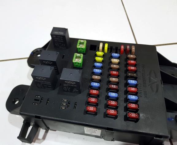
The photo shows an example.
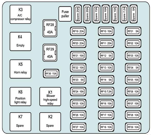
| Diagram | |
|---|---|
|
|
| No. | Purpose |
| RF01 | Dashboard illumination dimmer |
| RF02 | Vehicle speed sensor (for vehicles with manual transmission) |
| RF03 | ABS system |
| RF04 | Air conditioning control panel |
| RF05 | Cigarette lighter fuse Chery Tiggo 3 |
| RF06 | Dashboard |
| RF07 | Audio system |
| RF08 | Diagnostic connector |
| RF09 | Dashboard |
| RF10 | Rear window cleaner and washer |
| RF11 | Windshield wiper and washer |
| RF12 | Relay Coils:
|
| RF13 | Airbag System (SRS) |
| RF14 | Audio system |
| RF15 | Switch for adjusting the position of the outside rearview mirrors |
| RF16 | Seat heating (availability depends on equipment) |
| RF17 | Transmission control unit (TCU)/ECM/immobilizer system |
| RF18 | BCM |
| RF19 | Air conditioning compressor relay |
| RF20 | Sunroof (availability depends on equipment) |
| RF21 | Key left in ignition sensor |
| RF22 | Spare |
| RF23 | Sunroof sensors (availability depends on equipment) |
| RF24 | Horn relay |
| RF25 | Air conditioning control panel |
| RF26 | immobilizer system |
| RF27 | Heated exterior mirrors (availability depends on equipment) |
| RF28 | Ignition switch AM2 |
| RF29 | Ignition switch AM1 |
| RF30 | Electric outlet |
| K1 | High ventilation speed relay |
| K3 | A/C compressor relay |
| K5 | Horn relay |
| K6 | Position Lamp Relay |
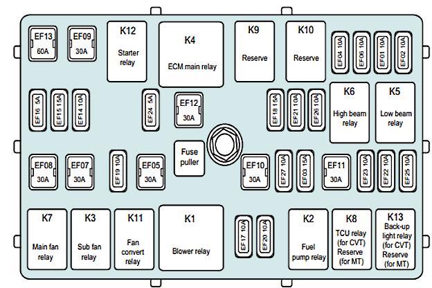
In the engine compartment
Depending on the configuration, there may be two blocks responsible for protecting the electrical circuits of the car.
Main fuse box
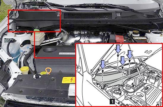
Located on the right side of the engine compartment. Unscrew the 4 fixing clips and remove the front right panel under the windshield (1).
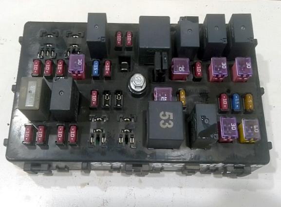
General view.
| Diagram | |
|---|---|
|
|
| No. | Description |
| EF01 | Left low beam headlight |
| EF02 | Right low beam headlight |
| EF03 | Fuel pump fuse |
| EF04 | Left high beam headlight |
| EF05 | Fan relay |
| EF06 | Right high beam headlight |
| EF07 | Additional fan |
| EF08 | Main fan |
| EF09 | Starter |
| EF10 | Transmission control unit (TCU) (for vehicle with CVT) |
| Spare (for vehicles with manual transmission) | |
| EF11 | Spare |
| EF12 | Main relay of the control unit |
| EF13 | BCM |
| EF14 | reversing lamp |
| EF15 | Transmission control unit (TCU) (for vehicle with CVT) |
| Spare (for vehicles with manual transmission) | |
| EF16 | Generator |
| EF17 | Right position/registration plate lights |
| EF18 | Spare |
| EF19 | Fan relay coil |
| EF20 | Left marker lights |
| EF21 | Spare |
| EF22 | Engine management |
| EF23 | Stoplight switch |
| EF24 | Winding of the main relay of the control unit |
| EF25 | Oxygen sensor |
| EF26 | Ignition coil |
| EF27 | ECM |
| K1 | Ventilation relay |
| K2 | Fuel pump relay |
| K3 | Auxiliary Fan Relay |
| K4 | Engine ECU Main Relay |
| K5 | low beam relay |
| K6 | high beam relay |
| K7 | Main fan relay |
| K8 |
|
| K9 | Reserve |
| K10 | Reserve |
| K11 | Fan conversion relay |
| K12 | Starter relay |
| K13 |
|
Additional fuse box

It is installed only on cars with 2.0 L CVT engine. It is located on the left side of the engine compartment.
| Diagram | |
|---|---|

|
|
| No. | Purpose |
| CF01 | Spare |
| CF02 | Engine cooling fan (low speed) |
| CF03 | Engine cooling fan (high speed) |
| K1 | Fan relay (low speed) |
| K2 | Fan relay (high speed) |
