Table of Contents
In this article, we will take a detailed look at the fuse diagrams for the Chery J3 / Cielo / Skin cars (first generation / A3 index): 2008, 2009, 2010, 2011, 2012, 2013, 2014, 2015 of release.

Fuse number 6 in the upper cabin block is responsible for protecting the electrical circuit of the cigarette lighter.
In the engine compartment
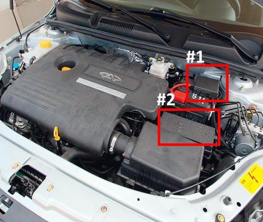
There are two distribution blocks responsible for protecting the electrical components of the car.
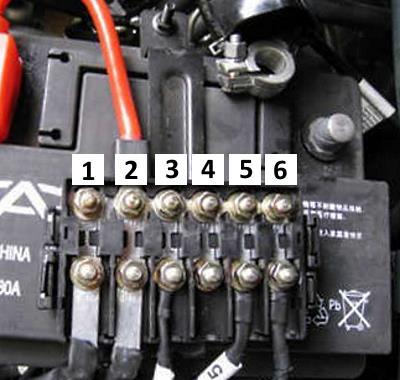
Fuse box #1
Located on the positive terminal of the battery.
| Diagram | ||
|---|---|---|
|
||
| No. | Description | Amps |
| 1 | Fuse box in the cabin | 100 |
| 2 | Battery charging and engine start system | 150 |
| 3 | Buzzer, parking alarm system, power windows, fog lights and lamp | 40 |
| 4 | Electric electric power steering | 50 |
| 5 | Electrical equipment of the engine compartment | 50 |
| 6 | Buzzer, clearance lamps, license plate lighting, direction indicators, interior lighting, mirrors, heated rear window, power windows, washers, lock | 80 |
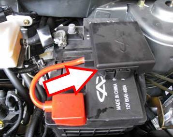
Fuse box #2
Located next to the battery. To access, you need to remove the plastic cover.
General view.
| Diagram | ||
|---|---|---|

|
||
| No. | Description | Amps |
| R1 | Not involved | - |
| R2 | Engine management system (EMS) relay | - |
| R3 | Starter relay | - |
| R4 | Air Conditioning Fan Relay | - |
| R5 | Ignition lock relay (ON position) | - |
| R6 | ACC circuit relay | - |
| R7 | A/C compressor relay | - |
| R8 | Chery J3 / Cielo / Skin fuel pump relay | - |
| R9 | Relay circuit ACC1 | - |
| R10 | High Beam Relay | - |
| R11 | Relay low beam headlights | - |
| FB1 | Engine Management System (EMS) | 5 |
| FB2 | Speed sensor | 5 |
| FB3 | SRS module | 20 |
| FB4 | Not involved | 5 |
| FB5 | Reversing lamp, battery charging system | 10 |
| FB6 | ignition module | 15 |
| FB7 | Not involved | 7.5 |
| FB8 | ABS module | 5 |
| FB9 | Not involved | 7.5 |
| FB10 | Front oxygen sensor | 10 |
| FB11 | Rear oxygen sensor | 10 |
| FB12 | Camshaft Position Sensor, Evaporative Emission System | 20 |
| FB13 | Air conditioning fan | 30 |
| FB14 | High beam left headlight | 10 |
| FB15 | Heated washer nozzles | 7.5 |
| FB16 | air conditioner compressor | 15 |
| FB17 | Chery J3 / Cielo / Skin Fuel pump fuse | 15 |
| FB18 | Electronic Engine Management System (EMS) | 7.5 |
| FB19 | High beam right headlight | 10 |
| FB20 | Electric windows | 30 |
| FB21 | Power sunroof | 30 |
| FB22 | Transmission | 10 |
| FB23 | Seat heating | 15 |
| FB24 | ABS system | 5 |
| FB25 | Not involved | 10 |
| FB26 | Low beam left headlight | 15 |
| FB27 | Dipped beam right headlight | 15 |
| SB1 | Not involved | 30 |
| SB2 | Engine | 30 |
| SB3 | Starter | 30 |
| SB4 | ABS module | 40 |
| SB5 | 20 | |
| SB6 | Egnition lock | 30 |
| SB7 | Dashboard | 30 |
| SB8 | Seat adjustment | 40 |
In the passenger compartment
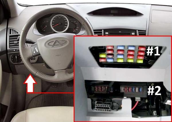
At the bottom of the dashboard, behind the trim, there are 2 fuse boxes.
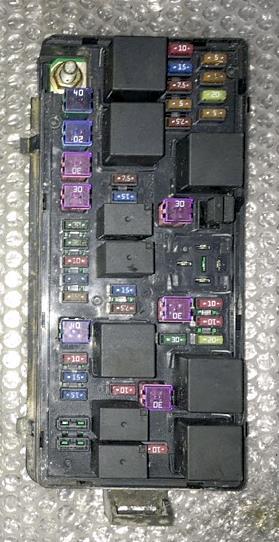
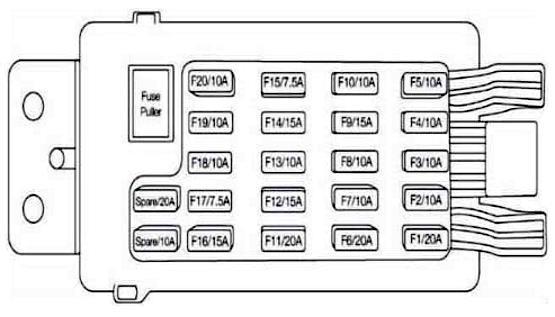
Fuse box #1

General view.
| Diagram | ||
|---|---|---|
|
||
| No. | Purpose | Amps |
| 1 | Spare | 20 |
| 2 | Buzzer, electric headlight range control position lights, registration plate light, fog lights and taillight, direction indicators and hazard warning lights, reversing light, interior lights, horns, outside rearview mirrors, parking alarm system, door lock control system , power windows, heated rear window and outside rear-view mirrors, trunk lid lock, windshield wiper and washer, audio system. | 10 |
| 3 | Spare | 10 |
| 4 | Electric headlight range control, parking lights, registration plate light, fog lights and lamp, interior lighting, electric power steering | 10 |
| 5 | reversing lamp | 10 |
| 6 | Electric outlet, Chery J3 / Cielo / Skin cigarette lighter fuse | 20 |
| 7 | To front fuse and relay box | 10 |
| 8 | Electric headlight range control, windshield wiper and washer | 10 |
| 9 | Diagnostic connector, fuel supply system, immobilizer | 15 |
| 10 | Air conditioning system, brake system, buzzer, position lamps, registration plate light, fog lights and lamp, direction indicators and hazard warning lights, fuel supply system, instrument panel, interior lighting, parking alarm system, door lock control system | 10 |
| 11 | Stop lights, brake system | 20 |
| 12 | Audio system | 15 |
| 13 | Trunk lid lock | 10 |
| 14 | Spare | 15 |
| 15 | Diagnostic connector, fuel supply system, immobilizer | 7.5 |
| 16 | Engine management system (EMS), brake system | 15 |
| 17 | Spare | 7.5 |
| 18 | Buzzer, electric headlight range control, position lamps, license plate lighting, fog lamps, direction indicators and hazard warning lights, reversing lamp, interior lighting, horns, exterior mirrors, parking alarm system, door lock control system, power windows, heated rear window and exterior mirrors, trunk lid lock, windshield wiper and washer, brake system, instrument panel, battery charging system | 10 |
| 19 | Air conditioning system | 10 |
| 20 | SRS module | 10 |
Fuse box #2
located below the first.
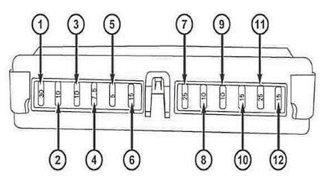
Description:
- Power windows 30A;
- Reserve 10A;
- Marker lamps (left) 10A;
- Control panel lighting 7.5A;
- Marker lamps (right) 5A;
- Door lock control system 15A;
- Windshield wiper and washer 25A;
- Interior lighting 10A;
- Horns 10A;
- Front fog lights 15A;
- Heated rear window and exterior rear-view mirrors 25A;
- Direction indicators and emergency light signaling 15A
View and print PDF:
