Table of Contents
The Uplander is a minivan produced and sold by Chevrolet from 2005 to 2009, replacing the Venture model. Built on the GMT201 platform. In this article, we will take a detailed look at the fuse diagrams for the the 1st generation Chevrolet Uplander 2005, 2006, 2007, 2008, 2009 model year with gasoline engines.

Here you will find the locations and photos of distribution boxes. Separately, we note the fuse responsible for the fuel pump.
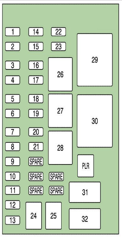
In the engine compartment
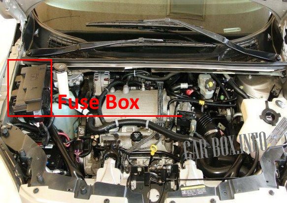
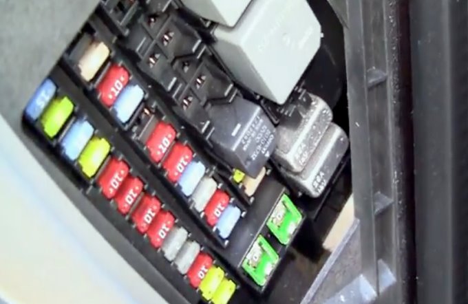
Located on the right side of the engine compartment, behind a protective cover.
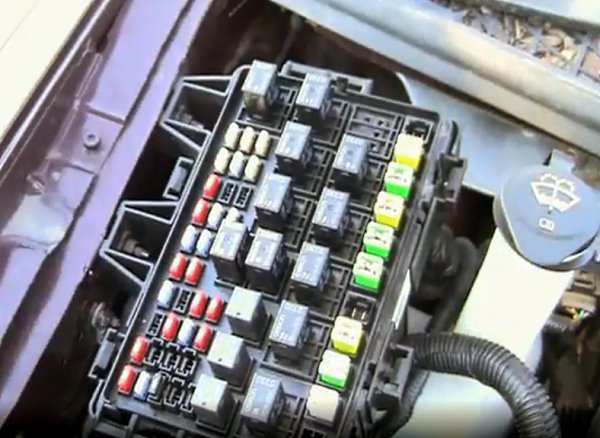
Access example.
| Diagram | |
|---|---|
|
|
| No. | Description |
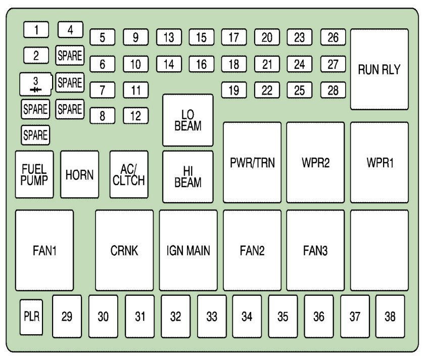
| Type J Case | |
| PLR | fuse puller |
| 29 | Fan 1 |
| 30 | starter valve |
| 31 | Anti-lock brake motor |
| 32 | Empty |
| 33 | Fan 2 |
| 34 | Front fan high |
| 35 | Main battery 3 |
| 36 | Rear heater |
| 37 | Main Battery 2 |
| 38 | Spare |
| Type Standard | |
| 1 | Right high beam |
| 2 | Chevrolet Uplander Fuel Pump Fuse |
| 3 | Diode |
| 4 | Left high beam |
| 5 | empty |
| 6 | air conditioner clutch |
| 7 | Sound signal |
| 8 | Left low beam |
| 9 | Powertrain Control Module, Electronic Throttle Control |
| 10 | empty |
| 11 | Gearbox valve |
| 12 | Right dipped beam |
| 13 | ABS anti-lock braking system |
| 14 | Powertrain Control Module Ignition |
| 15 | Electronic ignition |
| 16 | fuel injector |
| 17 | Climate control, RPA, Cruise control |
| 18 | Electronic throttle control |
| 19 | Engine sensor, evaporator |
| 20 | Airbags |
| 21 | empty |
| 22 | empty |
| 23 | Auxiliary |
| 24 | Windshield washer |
| 25 | AC/DC converter |
| 26 | Rear fan |
| 27 | Front fan |
| 28 | Front wiper |
| Relay modules | |
| RUN RLY | Starter |
| LO BEAM | dipped beam |
| FUEL PUMP | Fuel pump relay |
| HORN | Sound signal |
| AC/CLTCH | air conditioner clutch |
| HI BEAM | high beam |
| PWR/TRN | power unit |
| CAP2 | Wiper 2 |
| WPR1 | Wiper 1 |
| FAN 1 | Fan 1 |
| CRNK | Crank |
| IGN MAIN | Ignition |
| FAN2 | Fan 2 |
| FAN3 | Fan 3 |
| BLANK | empty |
In the passenger compartment
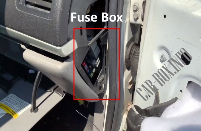
It is located at the end of the dashboard on the passenger side. To access, you need to remove the protective lining.
Access example.
| Diagram | |
|---|---|
|
|
| No. | Description |
| 1 | Trunk, door locks |
| 2 | Electronic level control |
| 3 | Rear wiper |
| 4 | Radio, DVD player |
| 5 | Interior lamps |
| 6 | OnStar® System |
| 7 | Keyless entry module |
| 8 | Heating, Ventilation, Air conditioning |
| 9 | cruise switch |
| 10 | Steering wheel lighting |
| 11 | Mirrors |
| 12 | Stop signal, turn signals |
| 13 | Heated seats |
| 14 | empty |
| 15 | Electronic level control |
| 16 | heated mirror |
| 17 | Center high brake light, reversing lights |
| 18 | Empty |
| 19 | Canister vent valve |
| 20 | park lamps |
| 21 | Electric sliding door |
| 22 | empty |
| 23 | empty |
| 24 | Left electric sliding door |
| 25 | Right sliding door with electric drive |
| 26 | empty |
| 27 | empty |
| 28 | Park lights, taillights |
| 29 | Auxiliary |
| 30 | Rear fog protection |
| PLR | fuse puller |
| 31 | Power seats |
| 32 | Power window |
View and print PDF:

Thanks for this great website and valuable information