In this article, we will take a detailed look at the fuse diagrams for the Chrysler 300 / 300C (LX; first generation): 2004, 2005, 2006, 2007 model year.
Fuses #9, #18 and #16 (2004-2005) in the trunk are responsible for the cigarette lighter and 12V power outlets.
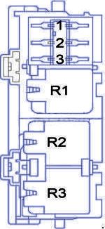
In the luggage compartment
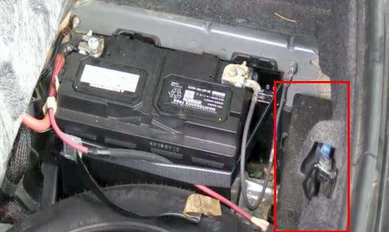
Fuse box located in the trunk under the reseve tire panel, near the battey.
General view.
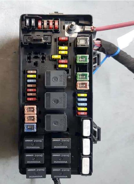
2006-2007 model year
Trunk block description for cars manufactured in 2006, 2007 years.
| Diagram | ||
|---|---|---|

|
||
| No. | Assigment | Amps |
| Type "Mini" | ||
| 6 | Fuel Pump Fuse | 20 |
| 8 | Ignition Switch/Airbag Control Module (ACM) | 15 |
| 9 |
|
20 |
| 14 | AC Heater Control/ Cluster/Sentry Key Remote Keyless Entry | 10 |
| 15 | Trailer Tow Brake Module - if installed | 20 |
| 17 | Cluster | 20 |
| 18 | Selectable 12V Power Outlet / Cigar | 20 |
| 19 | Stop Lights | 10 |
| 27 | Airbag System / Airbag Control Module (ACM) | 10 |
| 28 | Curtain Airbag - if installed | 10 |
| 29 | Anti-lock Brakes Module (ABS) - if installed/Cluster/Front Control Module (FCM)/Powertrain Control Module (PCM)/Sentry Key Remote Keyless Entry/Stop Lights | 5 |
| 30 | Door Modules/Power Mirrors - if installed / Steering Control Module | 10 |
| 35 |
|
5 |
| 36 |
|
20 |
| 37 | Transmission - NAG1 | 15 |
| 38 | Analog Clock/Cargo Light/Overhead Console | 5 |
| 39 | Mirrors Heater | 10 |
| 40 |
|
5 |
| 41 |
|
10 |
| Cartridge Fuses | ||
| 1 | Ignition Off Draw (IOD) | 60 |
| 2 | Battery | 40 |
| 4 | Battery | 40 |
| 5 | Seats Heater | 30 |
| 42 | Front Blower Motor | 30 |
| 43 |
|
30 |
| 44 |
|
20 |
| 11* |
|
25 |
| 12* | Passenger Seat Switch | 25 |
| 13* | Door Modules - except base/ Driver Door Lock Switch - base/Driver Express Power Window Switch - if equipped/ Passenger Door Lock Switch - base | 25 |
| * | circuit breakers: self-resetting fuses | |
2004-2005 model year
Trunk block description for cars manufactured in 2004, 2005 years.
| Diagram | ||
|---|---|---|
|
|
||
| No. | Assigment | Amps |
| 1 | Ignition Off Draw | 60 |
| 2 | Battery | 40 |
| 4 | Battery | 40 |
| 5 | Heated Seat/Steering Column | 30 |
| 6 | Fuel Pump Fuse | 20 |
| 8 | Ignition Start/Run - Start | 15 |
| 9 |
|
20 |
| 10 | Rear Fog Lamp | 10 |
| 14 |
|
10 |
| 15 | Brake Light (5.7L Engine) | 20 |
| 16 |
|
20 |
| 18 | Cigar / Selectable 12V Power Outlet | 20 |
| 19 | Stop Lamp | 10 |
| 20 | Rear Wiper | 20 |
| 27 | Airbag/Occupant Classification Module | 10 |
| 28 | Curtain Airbag | 10 |
| 29 | Sentry Key/Remote Keyless Entry/Powertrain Control Module Ignition Feed | 5 |
| 30 | Steering Column Module/ Power Mirrors | 10 |
| 35 | Power Antenna/Garage Door Opener/Ignition Delay | 5 |
| 36 | Radio/Navigation | 20 |
| 37 | Transmission | 15 |
| 38 | Analog Clock/Garage Door Opener | 5 |
| 39 | Heated Mirror | 10 |
| 40 | Power Mirror | 5 |
| 41 |
|
10 |
| 42 | Automatic Temperature Control (ATC) Blower Motor | 30 |
| 43 | Rear Defroster | 30 |
| 44 | Audio Amp | 20 |
| 11* | Memory Module/Door Locks | 25 |
| 12* | Passenger Power Seat | 25 |
| 13* | Door Module Run/Acc/Delay | 30 |
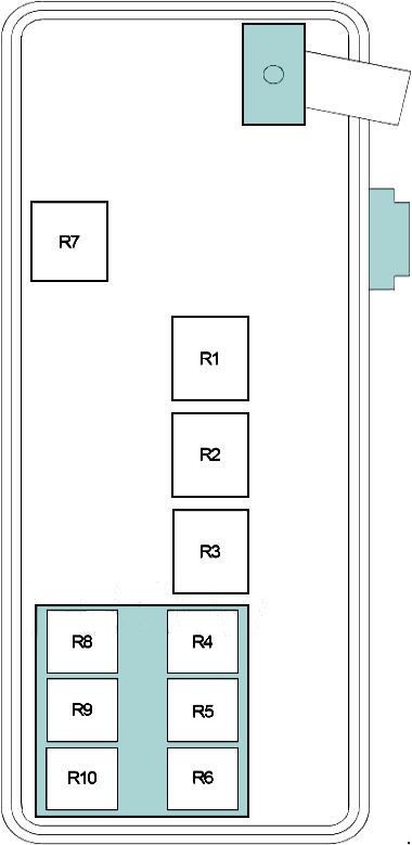
Relays
Assignment of relay modules in the trunk unit.
|
|
| R1 | Run Relay |
| R2 | Rear Window Defogger Relay |
| R3 | Accessory Delay |
| R4 | Transmission Control (NAG1) Relay |
| R5 | Rear Fog Lamp |
| R6 | Rear Wiper |
| R7 | Empty |
| R8 | Stop Lamp Inhibit |
| R9 | Chrysler 300 / 300C Fuel Pump Relay |
| R10 | Empty |
In the engine compartment
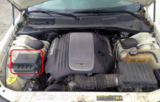
Located in the right side of the engine bay, behind the plastic cover.
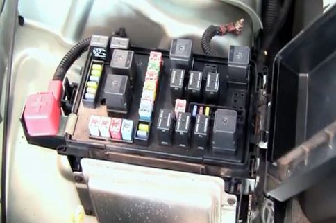
Access example.
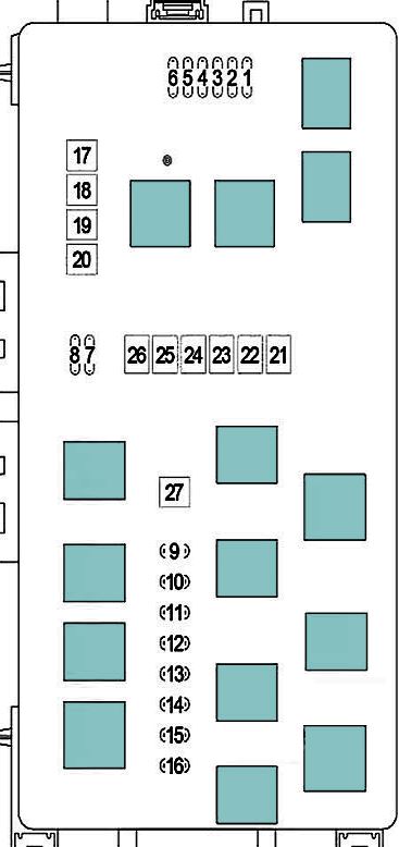
2006-2007 model year
Engine bay block description for cars manufactured in 2006, 2007 years.
| Diagram | ||
|---|---|---|
|
||
| No. | Assigment | Amps |
| 1 | Left High Intensity Discharge (HID) Headlight | 20 |
| 2 | Right High Intensity Discharge (HID) Headlight | 20 |
| 3 | Adjustable Pedals | 15 |
| 4 | AC Clutch/Horn | 20 |
| 5 | Headlight Washer | 20 |
| 6 | Front Control Module (FCM) | 15 |
| 7 | Fog Lights | 20 |
| 8 | Lights - License, Park, Side Marker, Stop. Turn | 15 |
| 9 | Front Control Module (FCM) | 15 |
| 10 | Powertrain Control Module (PCM)/Starter | 5 |
| 11 | Auto Shutdown/ Powertrain Control Module (PCM) | 25 |
| 14 | Powertrain Control Module (PCM) | 25 |
| 15 | Injectors, Ignition Coils | 20 |
| Cartridge Fuses | ||
| 17 |
|
30 |
| 18 | Windshield Wiper/ Washer | 30 |
| 19 | Radiator Fan | 50 |
| 20 | Starter | 20 |
| 21 | Anti-lock Brakes System (ABS) Pump Motor | 50 |
| 22 | AC Clutch/Radiator Fan High — Low | 40 |
| 23 | High Intensity Lighting (HID) | 50 |
| 24 | Radiator Fan - AWD | 60 |
| 25 | Front Control Module (FCM) | 30 |
| 26 | Transmission - RLE | 20 |
| 27 | Front Control Module (FCM) | 30 |
2004-2005 model year
Engine bay block description for cars manufactured in 2004, 2005 years.
| Diagram | ||
|---|---|---|
|
|
||
| No. | Assigment | Amps |
| 1 | High Beam Headlight Left Side | 20 |
| 2 | High Beam Headlight Right Side | 20 |
| 3 | Adjustable Pedal | 15 |
| 4 | Horn (Sound Signal) | 20 |
| 5 | Headlamp Washer | 25 |
| 6 | Front Control Module (FCM) | 15 |
| 7 | Fog Lamp | 20 |
| 8 | Park Lamp | 15 |
| 9 | Non ABS Brakes | 15 |
| 10 | Starter | 5 |
| 11 | Auto Shutdown/Powertrain Control Module (PCM) | 15 |
| 12 | Empty | — |
| 13 | Empty | — |
| 14 | Powertrain Control Module (PCM) | 20 |
| 15 | Injectors, Ignition Coils | 202 |
| 16 | Powertrain Control Module (PCM) | 20 |
| 17 | Antilock Brake System Valves (ABS) | 30 |
| 18 | Windshield Wiper/Washer | 30 |
| 19 | Radiator Fan | 50 |
| 20 | Starter | 20 |
| 21 | ABS Pump Motor | 50 |
| 22 | Radiator Fan High/Lovv | 40 |
| 23 | High Intensity Lighting | 50 |
| 24 | Empty | — |
| 25 |
|
30 |
| 26 | Transmission | 20 |
| 27 |
|
30 |
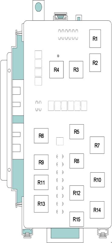
Relays
Main Fuse Box
Assignment of relay modules in the main engine unit.
|
|
| R1 | Horn Relay |
| R2 | Gasoline engine: Air Conditioner Compressor Clutch |
| R3 | Radiator Fan Control (High/Low Speed) |
| R4 | Radiator Fan Relay (High Speed) |
| R5 | Wiper On/Off Relay |
| R6 | Transmission Control Relay |
| R7 | Radiator Fan Control Relay |
| R8 | Wiper High/Low Relay |
| R9 | Starter Relay |
| R10 | Adjustable Pedals (except Memory) |
| R11 | Park Lamp Relay |
| R12 | Front Fog Lamp |
| R13 | Auto Shut Down |
| R14 | High Intensity Discharge |
| R15 | Empty |
Auxilary relay block (Diesel Only)
This unit is installed on vehicles with a diesel engine.
|
||
| R1 | PTC #3 | |
| R2 | PTC #2 | |
| R3 | PTC #1 | |
| 1 | PTC #1 Relay | 50 A |
| 2 | PTC #2 Relay | 50 A |
| 3 | PTC #3 Relay | 50 A |
