In this article, we will take a detailed look at the fuse diagrams for the Chrysler Aspen (first generation): 2006, 2007, 2008, 2009 model year.

Fuse #18 in the passenger compartment is responsible for the cigarette lighter and 12V power outlets.
In the engine compartment
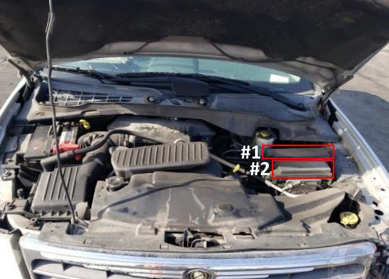
In the engine bay, next to each other, there are two blocks with fuses and relays.
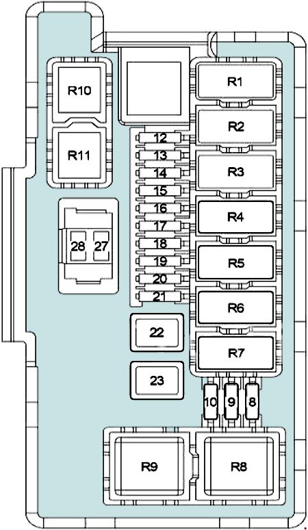
Fuse box #1
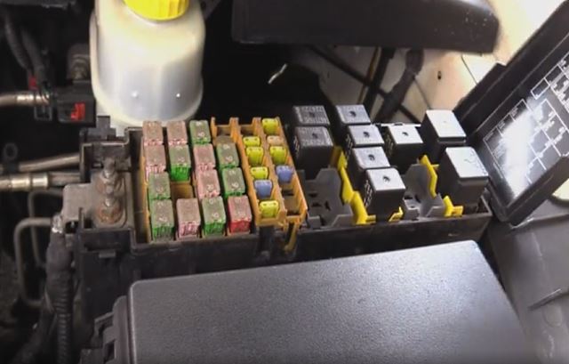
Access example.
| Diagram | ||
|---|---|---|

|
||
| No. | Description | Amps |
| R1 | Run/Start | |
| R2 | Run/Remote | |
| R3 | Empty | |
| R4 | Starter | |
| R5 | Transmission Control | |
| R6 | Air Conditioner Compressor Clutch | |
| R7 | Chrysler Aspen Fuel Pump Relay | |
| R8 | Stop Lamp Inhibit (Traction Control) | |
| R9 | Front Blower Motor | |
| R10 | Automatic Shut Down | |
| 1 | Starter Relay, Ignition Switch (Fuses "16", "18", "19", "32", "34" in the Passenger Compartment; #16 in the Engine Compartment), Run/Start Relay | 30 A |
| 2 | Integrate Power Module (Wiper High/Low Relay, Wiper On/Off Relay) | 30 A |
| 3 | Brake Provision Module | 40 A |
| 4 | Ignition Switch (Fuse (Passenger Compartment): "25"), Sunroof Motor, Fuse (Passenger Compartment): "35" | 30 A |
| 5 | Driver/Passenger Seat Switch, Heated Seat Module, Seat Memory Module | 40 A |
| 6 | Run Remote Relay | 20 A |
| 7 | Front Blower Motor Relay, Run/Remote Relay | 40 A |
| 8 | Accessory Relay (Circuit Breaker, Fuse (Passenger Compartment): "3") | 40 A |
| 9 | Empty | - |
| 10 | Automatic Shut Down Relay (Powertrain Control Module, ASD Relay, Ignition Coil, Fuel Injector, Ignition Capacitor) | 30 A |
| 11 | Liftgate Power Module | 40 A |
| 12 | Rear Window Defogger Relay (Fuse #2 in the interior), Shift Motor/Mode Sensor Assembly, T-Case Brake | 40 A |
| 13 | Rear Blower Motor Relay | 30 A |
| 14 | ABS | 40 A |
| 15 | Fuses "7", "8", "9", "10", "33" in the interior | 50 A |
| 16 | Starter Relay, Cluster, Powertrain Control Module, Front Control Module | 10 A |
| 17 | Empty | - |
| 18 | Fuel Pump Fuse | 20 A |
| 19 | Next Generation Controller (NGC) | 20 A |
| 20 | 115V Power Inverter | 25 A |
| 21 | ABS System | 20 A |
| 22 | Next Generation Controller (NGC) | 20 A |
| 23 | Trailer Tow Connector | 20 A |
| 24 | Air Conditioner Compressor Clutch Relay | 15 A |
| 25 | Stop Lamp Switch | 15 A |
| 26 | Empty | - |
| 27 | Ignition Switch (Instrument Cluster) | 10 A |
| 28 | Empty | - |
Fuse box #2
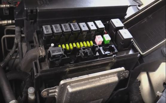
Access example.

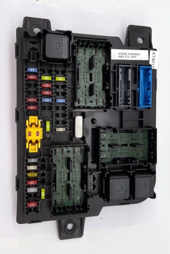
General view.
| Diagram | ||
|---|---|---|
|
||
| No. | Description | Amps |
| R1 | Wiper On/Off | |
| R2 | Wiper High/Low | |
| R3 | Horn Relay | |
| R4 | Wiper Rear | |
| R5 | Left Stop/Turn Trailer Tow Relay | |
| R6 | Right Stop/Turn Trailer Tow Relay | |
| R7 | Park Lamp Relay | |
| R8 | Radiator Fan (High) Relay | |
| R9 | Radiator Fan (Low) Relay | |
| R10 | Fog Lamp | |
| R11 | Adjustable Pedals | |
| 8 | Left Front Park/Turn Lamp, Left Front Marker Side Lamp, Left Tail/Stop/Turn Lamp, License Lamp | 10 A |
| 9 | Trailer Tow Connector (Park Lamps) | 10 A |
| 10 | Right Front Park/Turn Lamp, Right Front Marker Side Lamp, Right Tail/Stop/Turn Lamp | 10 A |
| 12 | Front Control Module | 20 A |
| 13 | 20 A | |
| 14 | Adjustable Pedals Relay | 20 A |
| 15 | Fog Lamps | 20 A |
| 16 | Horn | 20 A |
| 17 | Rear Wiper | 20 A |
| 18 | Front Control Module | 20 A |
| 19 | Left Stop/Turn Trailer Tow Relay (Trailer Tow Brake Lamp Relay Control, Trailer Connector) | 20 A |
| 20 | Front Control Module | 20 A |
| 21 | Right Stop/Turn Trailer Tow Relay (Trailer Tow Brake Lamp Relay Control, Trailer Connector) | 20 A |
| 22 | Front Control Module | 30 A |
| 23 | Radiator Fan (High&Low) Relay | 40 A |
| 27 | Front Control Module, Fuses #11, #12 in the interior fuse box | 30 A |
| 28 | Fuses #13, #14 in the passenger compartment | 30 A |
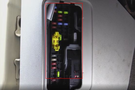
In the passenger compartment
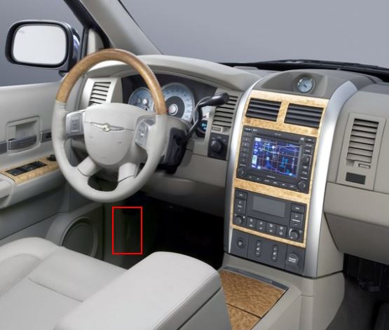
Fuse box located near the park brake pedal in the left side kick panel behind a plastic cover
Access example.
General view.
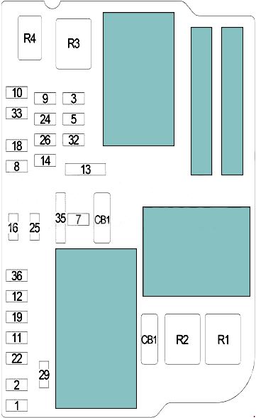
| Diagram | ||
|---|---|---|
|
||
| No. | Description | Amps |
| CB1 | Moonroof Motor, Power Window | 25 A |
| CB2 | Empty | - |
| R1 | Rear Window Defogger | |
| R2 | Rear Blower Motor | |
| R3 | Accessory Relay | |
| R4 | Empty | |
| 1 | Empty | - |
| 2 | Power Mirror / Mirrors Heater | 10 A |
| 3 | 12V Power Outlet in the Instrument Panel | 20 A |
| 4 | Empty | - |
| 5 | Empty | - |
| 6 | Empty | - |
| 7 | Radio Amp | 25 A |
| 8 | Mirror Switch and Memory Module | 10 A |
| 9 | Cluster | 20 A |
| 10 | 15 A | |
| 11 | Monitor, Satellite Digital Audio Receiver (SDAR), Digital Video Disc (DVD) | 10 A |
| 12 | Radio | 25 A |
| 13 | A/C Heater Control (Automatic A/C) | 15 A |
| 14 | Electronic Overhead Module, Data Link Connector, Hands-Free Module, Sentry Key Remote Entry Module, Air Conditioner Compressor Clutch Relay, Fuel Pump Relay, Powertrain Control Module, Bluetooth, Compass/Trip Computer (CMTC) | 15 A |
| 15 | Empty | - |
| 16 | Occupant Classification and Restraint Controller Module, Passenger Airbag On/Off Indicator Lamp | 10 A |
| 17 | Empty | - |
| 18 | Sentry Key Remote Entry Module, Integrate Power Module, Air Conditioner Compressor Clutch Relay, Fuel Pump Relay, Powertrain Control Module, Next Generation Controller (NGC) | 10 A |
| 19 | Cluster, Transfer Case Selector Switch, Driver/Passenger Heated Seat Switch, Inside Rearview Mirror, Infrared Sensor | 10 A |
| 20 | Empty | - |
| 21 | Empty | - |
| 22 | Empty | - |
| 23 | Empty | - |
| 24 | A/C Heater Control (Manual A/C), Rear A /C Heater Control (Automatic A/C), Rear Blower Motor Relay, Rear Window Defogger Relay | 10 A |
| 25 | Occupant Restraint Controller Module | 10 A |
| 26 | ABS System, Stop Lamp Inhibit (Traction Control), Steering Angle Sensor (Traction Control), Dynamics Sensor (Traction Control) | 10 A |
| 27 | Empty | - |
| 28 | Empty | - |
| 29 | Rear Park Assist, Second Row Heated Seats | 20 A |
| 30 | Empty | - |
| 31 | Empty | - |
| 32 | Heating & Air Conditioning (with ATC) | 15 A |
| 33 | Empty | 10 A |
| 36 | Ignition Run/Start Unlock | 20 A |
| 35 | 12V Power Outlets and cigarette lighter fuse | 20 A |
View and print PDF:

I asked where cig lighter fuse was why it told me at top of page fuse #18 is responsible for cig lighter and 12v power outlets, but in the diagram and corresponding list #35 is responsible