Table of Contents
The Dodge Caliber replaced the Neon, discontinued in 2005, and was produced between 2006 and 2012 in Illinois. The car was positioned as a 5-door hatchback, however, according to its external data, it is quite comparable with a station wagon and even a crossover. In this material, we will analyze in detail the Dodge Caliber fuse diagrams (PM index) 2006, 2007, 2008, 2009, 2010, 2011, 2012 of release.
Here you will find the locations and photos of distribution boxes. The fuse responsible for the “cigarette lighter” is highlighted in bold.
In the engine compartment
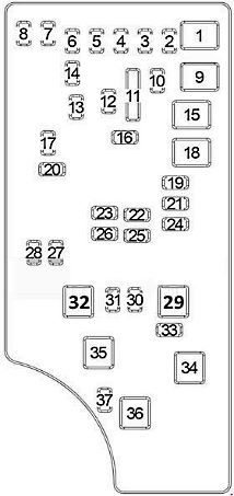
Main fuse box
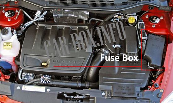
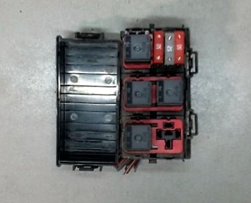
It is located on the right side of the engine compartment near the air filter.
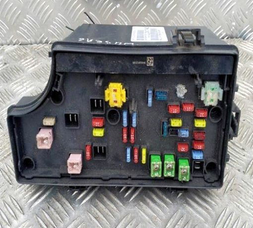
General view.
| Diagram | ||
|---|---|---|
|
||
| No. | Description | A |
| 1 | Reserve | - |
| 2 | All-wheel drive control unit (4WD/AWD) | 20 |
| 3 | Stop lamp switch | 10 |
| 4 | Ignition switch, keyless entry system, engine control unit, TIPM | 10 |
| 5 | Reserve | - |
| 6 | Airbag control unit, sun visor lights, Hands Free, satellite receiver, power mirrors | 10 |
| 7 | Fuse protection no.: "14", "20", "21" | 30 |
| 8 | Fuse protection no.: "6", "17", "19" | 30 |
| 9 | Reserve | - |
| 10 | instrument cluster | 20 |
| 11 | Reserve | - |
| 12 | inverter | 20 |
| 13 | Interior lighting | 20 |
| 14 | instrument cluster | 10 |
| 15 | Cooling fan relay (low/high speed), cooling fan relay (medium/high speed) | 50 |
| 16 | Outlet (dashboard), outlet (AC), sunroof, rear wiper, cigarette lighter fuse Dodge Caliber | 15 |
| 17 | Transmission Control Module (CVT), Steering Wheel Control Module, Keyless Entry System | 10 |
| 18 | Main relay (fuse protection no.: "23", "26", "32") | 40 |
| 19 | Audio system amplifier, subwoofer | 20 |
| 20 | Audio system | 15 |
| 21 | Anti-theft system, siren | 10 |
| 22 | Heating and air conditioning control unit, compass | 10 |
| 23 | Gasoline engine: Ignition coils, ignition coil capacitor | 15 |
| Diesel engine: Glow plug control unit, mass air flow sensor | 15 | |
| 24 | Sunroof | 25 |
| 25 | Heated mirrors | 10 |
| 26 | Petrol engine: Injectors, camshaft position sensor | 15 |
| Diesel Engine: Air Conditioning Compressor, Exhaust Gas Recirculation (EGR) | 15 | |
| 27 | Airbag control module | 10 |
| 28 | 10 | |
| 29 | Reserve | - |
| 30 | Heated seats | 20 |
| 31 | Diesel Engine: Auxiliary Heater Relay #1, Auxiliary Heater Relay #2 | 10 |
| 32 | Petrol engine: Powertrain control unit | 30 |
| Diesel engine: Engine control unit | 30 | |
| 33 | Diagnostic Connector, Powertrain Control Module (Gasoline), Switch Block, Main Relay, Cooling Fan Relay (Low/Medium/High Speed), Fan Start Order | 10 |
| 34 | ABS system | 30 |
| 35 | ABS system | 40 |
| 36 | Reserve | - |
| 37 | Reserve | - |
Additional fuse box
General view.
| Diagram | ||
|---|---|---|

|
||
| No. | Relay modules | |
| R1 | Cooling fan (low/high speed) | |
| R2 | Cooling fan (fan activation order) | |
| R3 | Cooling fan (medium/high speed) | |
| R4 | Main relay | |
| R5 | empty | |
| No. | Circuit breakers | A |
| 6 | Auxiliary heater relay No. 2 (Diesel) | 25 |
| 8 | Auxiliary heater relay No. 1 (Diesel) | 25 |
| 10 | Glow Plug Control Unit (Diesel) | 50 |
View and print PDF:
