Fiat Marea is a family car, available as a sedan and station wagon (Weekend modification), produced by the Italian automaker. In this article, we will take a detailed look at the fuse box diagrams for the Fiat Marea / Weekend 1st generation (185) 1996, 1997, 1998, 1999, 2000, 2001, 2002, 2003 years of manufacture.
Here you will find the locations and photos of distribution boxes. The fuses responsible for the “Cigarette lighter” and “Fuel Pump” are highlighted in bold.
All electrical equipment

General layout of electronic equipment in the vehicle.
1. Electronic air conditioning control module;
2. Anti-theft system control module;
3. Battery;
4. Diagnostic connector (DLC) 1-1,2;
5. Diagnostic connector (DLC) 1 -1,6/1,8/2,0;
6. Diagnostic connector (DLC) 1 - 1,9TD/2,4TD;
7. Diagnostic Connector (DLC) 2 - ABS;
8. Diagnostic connector (DLC) 3 - 1,8;
9. Diagnostic connector (DLC) 3 - 1,9TD;
10. Power window control module, rear. - under the rear seat;
11. Engine control relay-1,8/2,0/1,9TD-100/2,4TD;
12. Relay 2 cooling fan motor relay-1,4/1,6;
13. Fog lamp relay;
14. Gasoline pump relay-1,8/2,0;
15. Fuse and relay box, underhood 1;
16. Fuse and relay box 2, underhood - except 2.4TD;
17. Fuse and relay box 2, underhood - 2,4TD;
18. Fuse and relay box - passenger compartment 1;
19. Fuse and relay box - passenger compartment 2;
20, 21. Additional fuses (engine management system 5A / 15A) -1,6;
22. Additional fuse (engine management system 30A) -1,8;
23, 24. Additional fuses (engine management system 7,5A / 15A) - 1,9TD-100;
25. Additional fuse (gasoline pump 15A) -1,4;
26. Additional fuse (fuel pump 15A) -1,8/2,0;
27. Additional fuse (heated oxygen sensor (HO2S)15A) -1,4;
28. Additional fuse (heated oxygen sensor (HO2S)15A) -2,0;
29. Dipped beam relay;
30. Heater fan motor resistor;
31. Horn 1;
32. Buzzer 2;
33. Relay for main ignition circuits;
34. Electronic immobilizer control module;
35. Gate indicator interrupter relay;
36. Inertia fuel cut-off switch under the driver's seat;
37. Multifunction control unit - functions: Central locking, power windows-front power windows, door mirror heaters, rear window heater, rear window heater, interior lamps;
38. Ambient air temperature sensor - in the door rearview mirror;
39. SRS electronic control module;
40. Electronic control module for transmission.
In the engine compartment

There are two fuse blocks in the underhood area. To access the main block No. 1, it is necessary to remove the protective cover by previously unscrewing one fixing screw.
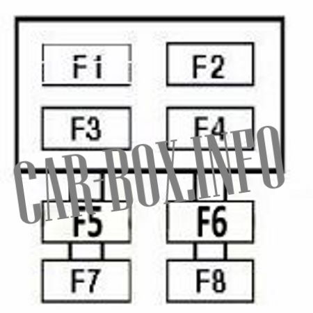
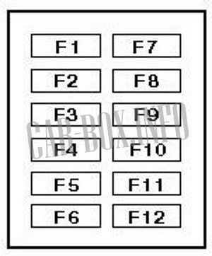
Fuse box #1
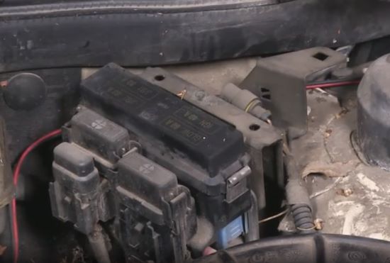
Access example.
| Diagram | ||
|---|---|---|
|
||
| No. | Description | A |
| F1 | Engine management system - petrol | 30 |
| F2 |
|
60 |
| F3 | Engine management | 40 |
| F4 | Fuse box in passenger compartment 1 | 80 |
| F5 | Cooling fan motor 1 | 30/40/50 |
| F6 | — | |
| F7 | Anti-Lock Braking System (ABS) | 60 |
| F8 | Cooling fan motor 2 - Diesel TD, except 1.9-100 without air conditioning | 40 |
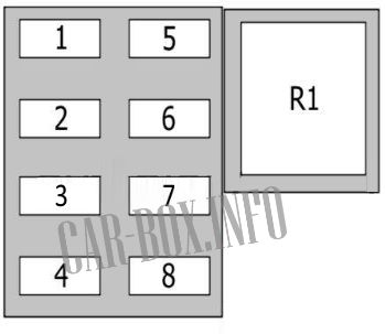
Fuse box #2
Diagram.

|
||
| No. | Description | A |
| F1 | Immobilizer | 10 |
| F2 | Anti-Lock Braking System (ABS) | 10 |
| F3 | Headlight washer/wipe system | 20 |
| F4 | Automatic transmission | 10 |
| F5 | Automatic transmission | 5 |
| 1 | Cooling Fan Motor Timer Relay - With A/C | |
| 2 | Cooling Fan Motor Relay 1 - With A/C | |
| 3 | Air conditioner compressor solenoid clutch relay | |
| 4 | Headlight washer pump relay | |
| 5 | Cooling fan motor relay 2 -1.8/2.0 with AC | |
| 6 | Start prohibition switch relay | |
| 7 | Gearbox oil cooler pump motor relay | |
| 8 | Electric motor relay of camshaft phase change actuator -2,0 | |
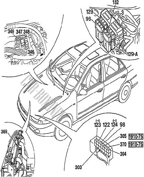
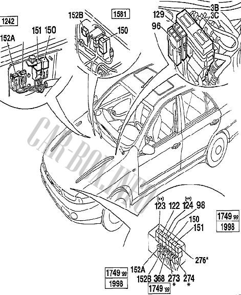
Individual components
Layout of the individual relays and fuses in the engine compartment of the vehicle.
| Diesel engines | |
|
|
| # | (••) Vehicles with air conditioning. |
| 3B/C | Fuse box |
| 96 | ABS fuse |
| 98 | Headlight washer relay |
| 122 | Cooling fan relay (low speed) |
| 123 | Cooling fan relay (high speed) |
| 124 | Air conditioner compressor relay |
| 129 | Cooling fan fuse |
| 129A | Second cooling fan fuse |
| 152 | Engine control unit fuse |
| 303 | Heater fuse (TD) |
| 304 | heater relay |
| 305 | Compressor shutdown relay (1910 TD-75) |
| 346 | Auxiliary heater relay |
| 347 | |
| 348 | Additional heater control unit |
| 349 | Auxiliary heater fuse |
| 369 | Cooling fan control unit |
| 370 | Inertia relay (1910 TD-75) |
| Gasoline engines | |
|
|
| # | (••) Vehicles with air conditioning. (*) 1581 with automatic transmission. |
| 3B-3C | Fuse distribution box |
| 96 | ABS fuse |
| 98 | Headlight washer relay |
| 122 | Cooling fan relay (low speed) |
| 123 | Cooling fan relay (high speed) |
| 124 | Air conditioner compressor relay |
| 150 | Engine control unit relay |
| 151 | Lambda probe relay |
| 152 | Engine control unit fuses |
| 152A | |
| 152B | |
| 273 | Automatic transmission fuses |
| 274 | |
| 276 | Starter relay |
| 368 | Relay (with diode) engine control unit |
In the passenger compartment
There are two distribution boxes here that are responsible for protecting the electrical circuits.
Main fuse box

The main distribution box is located behind the dashboard trim near the steering wheel. To access it, unscrew three fixing screws and remove the protective panel.
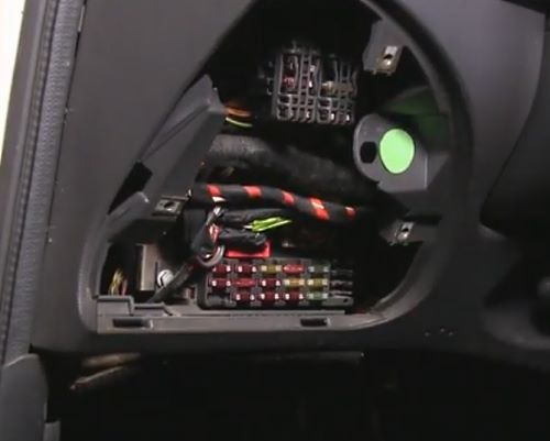
It consists of two divisions, the upper and the lower.
| Upper section diagram | ||
|---|---|---|
| No. | Description | A |
| Type #1 | ||
|
||
| F1 | central locking system | 20 |
| F2 | Fog lights | 15 |
| F3 | Safety Airbag | 7.5 |
| F4 | Rear view mirror heater on the doors | 7.5 |
| F5 | Sunroof | 20 |
| F6 | Power windows rear | 30 |
| F7 | Electric front power windows | 30 |
| F8 | Seat heater | 10 |
| R1 | Fog lights | - |
| Type #2 | ||
|
||
| F1 | Air Conditioning - Gasoline | 7.5 |
| F2 | Headlight washers | 20 |
| F3 | Cooling fan motor relay, engine management system, petrol immobilizer | 7.5 |
| F4 | Anti-Lock Braking System (ABS) | 10 |
| F5 | Air conditioner | |
| F6 | Engine management system, immobilizer- petrol | 7.5 |
| F7 | Audio system, interior lamps, telephone | 7.5 |
| F8 | Fog lights | 15 |
| F9 | Power windows rear | 25 |
| F10 | Power windows front | 25 |
| F11 | Fiat Marea cigarette lighter fuse, seat heaters, sunroof | 30 |
| F12 | Safety Airbag | 10 |
| Description of the lower section | ||
|---|---|---|

General view. |
||
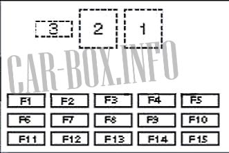
Diagram. |
||
| No. | Purpose of the fuses | A |
| F1 | Door mirror heater, rear window heater | 30 |
| F2 | Instrument cluster (2001^), emergency alarm system | 10 |
| F3 | Direction indicators, instrument cluster, brake lights | 10 |
| F4 | Anti-theft system, instrument cluster (^2000), interior lamps | 10 |
| F5 | Air conditioning system (AC)(^2000), horn (beep) | 20 |
| F6 | Headlight washers, rear window wiper/washer, windshield wiper/washer | 20 |
| F7 | Cigarette lighter fuse, heater/air conditioner | 20 |
| F8 | Headlight corrector, headlight washers, left headlight - dipped beam | 10 |
| F9 | Electric door mirrors, front left parking lamp, license plate illumination lamp, rear right parking lamp | 10 |
| F10 | Audio system, instrument cluster illumination, air conditioning/heating system, rear left parking lamp, license plate illumination lamp, front right parking lamp | 10 |
| F11 | Air conditioner | 30 |
| F12 | Right headlight dipped beam | 10 |
| F13 | Audio system, central locking, fog lights | 10 |
| F14 | Left headlight - high beam | 10 |
| F15 | Right headlight - high beam | 10 |
| Relay modules are located on the back side of the unit | ||
| 1 | Ignition Auxiliary Relay | |
| 2 | Rear defroster relay | |
| 3 | Horn relay | |
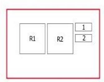
Auxilary fuse panel
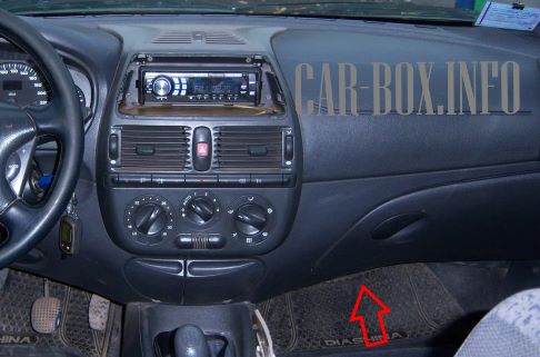
Located under the glove box on the passenger side.
|
|
| R1 | Fuel pump relay |
| R2 | injection system |
| 1 | injection system |
| 2 | Fuel Pump / Fuel Module |
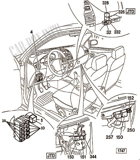
Individual components
Layout of the individual relays and fuses in the vehicle interior.
|
|
| № | Component |
| 3A/D | Upper fuse box |
| 4 | Lower fuse box |
| 5 | Dipped beam headlights relay |
| 32 | Fog lamp relay |
| 150 | Engine control unit relay (1.8 16V (1747), JTD) |
| 151 | Lambda probe relay |
| 152 | Engine control unit fuse (1.8 16V (1747), JTD) |
| 250 | Fuel pump fuse (1.8 16V (1747)) |
| 257 | Fuel pump relay (1.8 16V (1747)) |
| 326 | heater relay |
| 328 | Emergency alarm relay |
| 332 | Ignition relay |
