Fiat Multipla is a compact van of the Italian company, produced from 1998 to 2010. It is based on the Brava platform. Features of the car are its width and the presence of three seats in front. Subsequently, the same performance was applied to the Honda FR-V. In this article, we will take a detailed look at the fuse box diagrams for the Fiat Multipla 1st generation (factory index 186) 2004, 2005, 2006, 2007, 2008, 2009, 2010, 2011 years of manufacture.

Here you will find the locations and photos of distribution boxes. The fuses responsible for the “Cigarette lighter” and “Fuel Pump” are highlighted in bold.
In the engine compartment
There are three distribution boxes here, which are responsible for protecting the vehicle's electrical circuits.
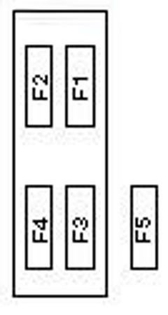
Primary fuse box
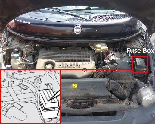
The first underhood unit is located on the right side of the engine compartment behind the protective cover.
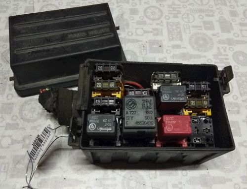
General view.
| Diagram | ||
|---|---|---|

|
||
| No. | Description | A |
| F1 | Additional heater | 20 |
| F2 | Immobilizer | 7.5 |
| F3 | Engine management (Euro 3) | 10 |
| F4 | Anti-Lock Braking System (ABS) | 10 |
| F5 | Engine management | 20 |
| F6 | Headlight washers | 20 |
| F7 | Engine management, immobilizer | 7.5 |
| 1 | Fuel pump relay | |
| 2 | Engine cooling fan relay | |
| 3 | ||
| 4 | Headlight washer pump delay relay | |
| 5 | Air conditioner compressor clutch relay | |
| 6 | Fuel heater relay | |
Additional fuse panel
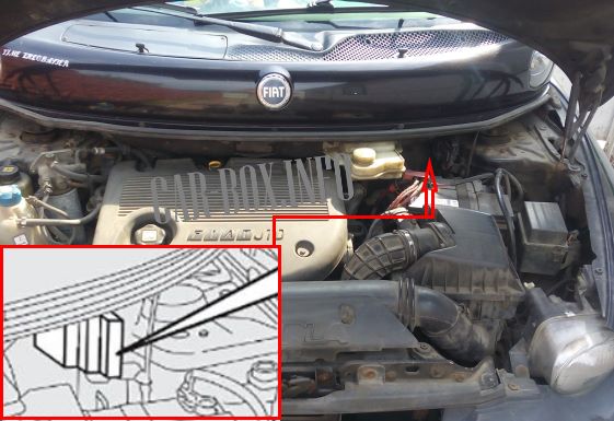
A second underhood fuse box is located on the bulkhead (closer to the passenger compartment).
|
||
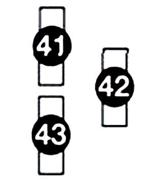
| No. | Description | A |
| 41 | Engine cooling fan (with heater) | 40 |
| Engine cooling fan (with air conditioning) | 50 | |
| 42 | glow plugs | 60 |
| 43 | ABS system | 60 |
Power fuse panel

Located next to the battery.
| Diagram | ||
|---|---|---|
|
||
| F1 | Protection of interior fuse box circuits | 80 |
| F2 | Power Window Relay, Cabin Fuse/Relay Box, Dipped Headlight Relay, Ignition Auxiliary Circuit Relay | 60 |
| F3 | Ignition lock | 30 |
| F4 | Engine management | 30 |
| F5 | - | |
Individual relay modules
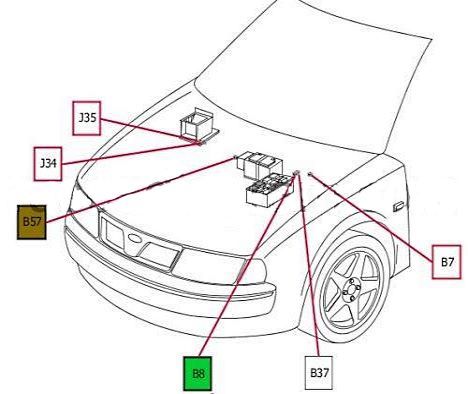
Some relay modules are placed separately:
- J35: fan;
- J34: air conditioning compressor;
- B57: Taxi package 7.5A;
- B8: Cooling system fan 30/40A;
- B7: ABS/ESP 60A
In the passenger comparment
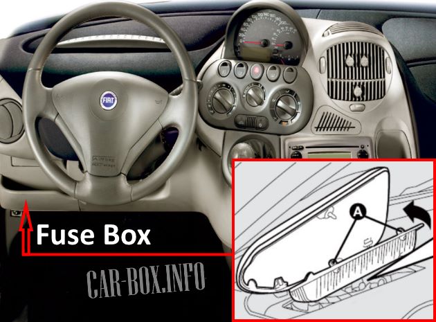
Placed on the driver's side behind the change box.
| Diagram | ||
|---|---|---|

|
||
| No. | Description | A |
| F1 | Right headlight - high beam | 10 |
| F2 | Left headlight - high beam | 10 |
| F3 | Power windows, combination shifter, rear fog lights, sunroof, navigation system | 20 |
| F4 | Left headlight - dipped beam | 10 |
| F5 | Air conditioner/heater fan motor | 30 |
| F6 | Audio unit illumination lamp, cigarette lighter lamp, navigation system illumination lamp, right license plate illumination lamp, right side/rear lamps | 10 |
| F7 | Heater control lamp(s), left license plate light, left side/rear lamps | 10 |
| F8 | Headlight corrector, right headlight - dipped beam | 10 |
| F9 | Air conditioner compressor clutch, Fiat Multipla Cigarette Lighter Fuse | 15 |
| F10 | Headlight washers, rear window washer / wiper, windshield washer / wiper | 20 |
| F11 | Horn (beep) | 20 |
| F12 | Security alarm, alarm/central lock sensor, audio system, data link connector (DLC), interior lamps, instrument panel, instrument illumination, telephone | 10 |
| F13 | Airbag, alarm, anti-lock brakes (ABS), audio system, clutch pedal position switch (CPP) (diesel), indicators/alarm, instrument cluster, parking assist sensors, reverse lights, brake lights, telephone | 15 |
| F14 | Indicators/alarm lights | 10 |
| F15 | Heated rear-view mirrors, heated rear window | 30 |
| F16 | Ignition Auxiliary Relay | 7.5 |
| F17 | AC recirculation motor, electric exterior mirrors, air conditioner/heater fan motor relay | 7.5 |
| F18 | central locking system | 20 |
| F19 | Optional power connector | 25 |
| F20 | Fog lights | 15 |
| F21 | Power seats | 25 |
| F22 | Heated mirrors | 7.5 |
| F23 | Safety Airbag | 7.5 |
| F24 | Power windows (rear) | 25 |
| F25 | Navigation system, refrigerator, sunroof | 25 |
| 1 | Ignition Auxiliary Relay 1 | |
| 2 | Heated rear window relay | |
| 3 | Horn relay | |
| 4 | Ignition Auxiliary Relay 2 | |
