The Ford Escape has been produced from 2000 to the present in 4 generations with various engine modifications, including hybrid ones. It is also known in the European market under the name Ford Maverick. 1st generation was produced in 2001, 2002, 2003, 2004, 2005, 2006 and 2007. During this time, the car received an update. The 2nd generation was assembled in 2008, 2009, 2010, 2011 and 2012. It did not receive any fundamental design changes, therefore the location of the fuse and relay blocks for the first and second generations is the same. In our material you will find a description of the 1st and 2nd generation Ford escape fuses and relays, with block diagrams and photographs. The fuse responsible for the “Cigarette lighter” is highlighted in bold.

The design of the blocks and the purpose of their elements in the Ford Escape (Ford Maverick) may differ from the one presented and depends on the year of manufacture, the level of equipment and the country of delivery.
In passenger compartment
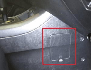
Fuse box located under the dashboard (lower part of the torpedo), on the passenger side and is covered by a protective cover. To access, simply pry with a flat screwdriver by the special notch in the cover.
Type 1
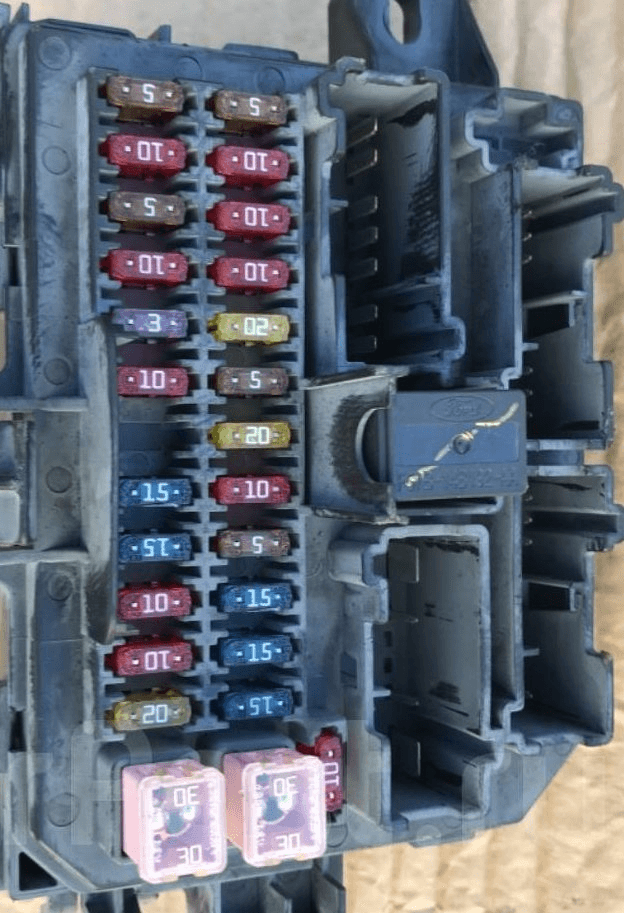
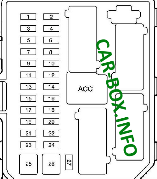
General view.
| Diagram | |
|---|---|
|
|
| № | Description |
| 1 | 5A Electro - pneumatic valve for the fuel vapor battery |
| 2 | 5A Fan relay, heated rear window |
| 3 | 10A Rear door glass wiper and washer motor |
| 4 | 10A 4WD control unit, instrument cluster |
| 5 | 5A ABS and SRS control unit |
| 6 | 10A Hazard warning lights, reversing lights |
| 7 | 10A Transponder signal amplifier, SRS control unit |
| 8 | 10A Instrument cluster, selector lock relay |
| 9 | 3A Relay for engine control unit and automatic transmission, fan relay, air conditioning relay |
| 10 | 20A Windshield wiper motor, windshield washer motor, intermittent wiper relay |
| 11 | 10A Starter relay, ignition key lock solenoid valve |
| 12 | 5A Radio and clock |
| 13 | Reserve |
| 14 | 20A Cigarette lighter |
| 15 | 15A Tail lamps, spotlights, trailer wiring relay |
| 16 | 10A Instrument panel, power mirrors, electrical control unit |
| 17 | 15A Moonroof |
| 18 | 5A Illumination of the instrument cluster and instrument panel switches |
| 19 | 10A Subwoofer |
| 20 | 15A Direction indicators, direction indicator indicators, hazard warning lights |
| 21 | 10A Trailer side lights |
| 22 | 15A Reserve |
| 23 | 15 / 20A Buzzer |
| 24 | 15A Brake lights, ABS control unit, engine and automatic transmission control unit, automatic transmission shift solenoid valves |
| 25 | 30A Power windows |
| 26 | 30A Central locking, electrical control unit, power seats |
| 27 | 10A Radio, instrument cluster, interior lighting |
| ACC | Relay for additional equipment installation |
| The fuse number 14, 20A, is responsible for the Ford Escape cigarette lighter. | |
Type 2
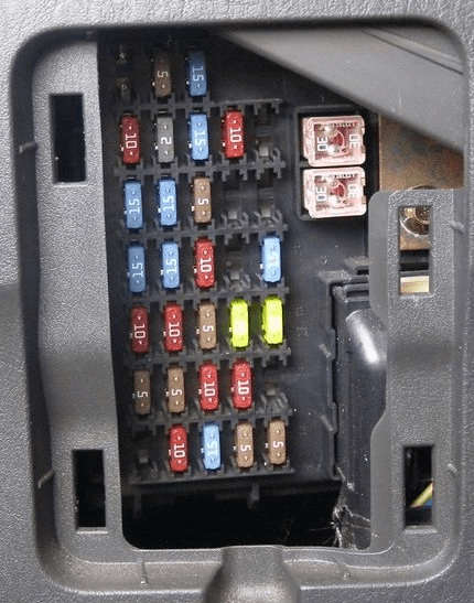
General view.
| Diagram | |
|---|---|
|
|
| № | Description |
| 1 | 15A Trailer lamps |
| 2 | 5A Radio (backlight) |
| 3 | 15A Front and rear parking lights |
| 4 | 10A Ignition switch |
| 5 | 2A Automatic transmission control unit relay, fuel pump relay, fan relay, No. 2 high / low fan speed |
| 6 | 15A Additional brake lights, brake lights, engine and automatic transmission control unit, ABS, cruise control |
| 7 | 10A Instrument cluster, OBD diagnostic socket, radio, electric side mirrors |
| 8 | 15A Fog lights |
| 9 | 30A Central locking, power seats |
| 10 | 15A Heated side mirrors |
| 11 | 15A Sunroof |
| 12 | 15A Radio |
| 13 | Reserve |
| 14 | Reserve |
| 15 | 30A Power window drive |
| 16 | 15A Subwoofer |
| 17 | 15A Low beam |
| 18 | 18A AWD system |
| 19 | 15A Anti-theft system |
| 20 | 20A Buzzer |
| 21 | 10A Rear door glass wiper and washer motor |
| 22 | 10A Interior rearview mirror, instrument cluster |
| 23 | 5A Radio (power) |
| 24 | 20A Cigarette lighter |
| 25 | 20A Windshield washer and wiper motor |
| 26 | 5A Air Conditioner |
| 27 | 5A Cruise control switch |
| 28 | 10A Instrument cluster |
| 29 | 10A Reversing lights |
| 30 | Reserve |
| 31 | Reserve |
| 32 | 10A Selector lock relay |
| 33 | 15A SRS control unit, front passenger airbag deactivation indicator, front passenger seat sensor |
| 34 | 5A ABS unit, cruise control |
| 35 | 5A Heated seats, four-wheel drive |
| For the front cigarette lighter, there is a fuse number 24 at 20A. | |
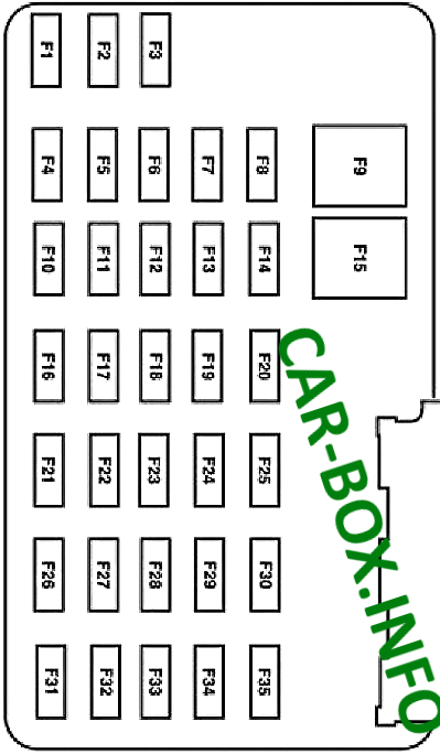
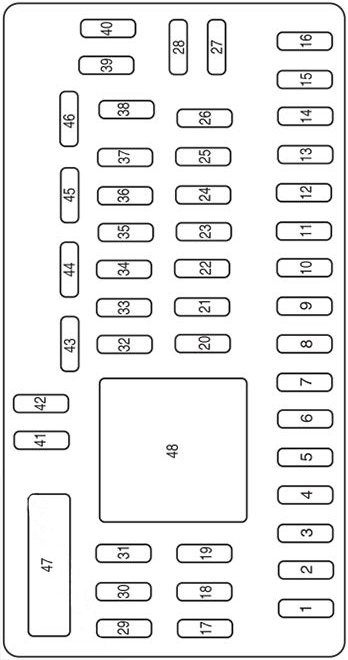
Type 3

General view.
| Diagram | |
|---|---|
|
|
| № | Description |
| 1 | 30A Not used (spare) |
| 2 | 15A Brake switch |
| 3 | 15A Timing module |
| 4 | 30A Moonroof |
| 5 | 10A Keypad Backlight, Brake Shift Interlock (BSI), SPDJB |
| 6 | 20A Direction indicators, brake lights |
| 7 | 10A Low beam headlights (left) |
| 8 | 10A Low beam headlights (right) |
| 9 | 15A Interior lighting |
| 10 | 15A Backlight |
| 11 | 10A All wheel drive |
| 12 | 7.5A Power Mirror Switch |
| 13 | 5A Not used (spare) |
| 14 | 10A FCIM (radio buttons), satellite radio, front display module |
| 15 | 10A Climate control |
| 16 | 15A Not used (spare) |
| 17 | 20A All motor power supplies, lifting gate unlocking, lifting windows unlocking |
| 18 | 20A Heated seats |
| 19 | 25A Rear wiper |
| 20 | 15A Diagnostic connector |
| 21 | 15A Fog lights |
| 22 | 15A Park lamps |
| 23 | 15A High beam headlights |
| 24 | 20A Signal relay |
| 25 | 10A Alarm |
| 26 | 10A Dashboard combination |
| 27 | 20A Ignition switch |
| 28 | 5A Radio |
| 29 | 5A instrument cluster |
| 30 | 5A Not used (spare) |
| 31 | 10A Limiter control module |
| 32 | 10A Not used (spare) |
| 33 | 10A Not used (spare) |
| 34 | 5A Anti-lock braking system (ABS) |
| 35 | 10A 4WD, Electric Power Steering (EPAS) Module, Parking Assist Module |
| 36 | 5A PATS transceiver |
| 37 | 10A Climate control |
| 38 | 20A Subwoofer / amplifier (radio) |
| 39 | 20A Radio, radio amplifier (for navigation only) |
| 40 | 20A Front cigarette lighter |
| 41 | 15A Driver / Passenger Door Lock Switches, Auto Dimming Mirror, Compass, Exterior Lights, Roof |
| 42 | 10A Not used (spare) |
| 43 | 10A Rear Wiper Logic, Heated Seat Relay, Instrument Cluster |
| 44 | 10A Not used (spare) |
| 45 | 5A Front wiper, blower motor relay |
| 46 | 7.5A OCS (limits), PADI (limits) |
| 47 | 30A Power Window Circuit Breaker |
| 48 | Delayed Access Relays |
| For the front cigarette lighter, there is a fuse number 40, 20A. | |
For rear and additional sockets, which is relevant for all generations, the fuses located in the block under the hood can also be responsible. Designated in the diagrams as - PWR1 and PWR2
Additional relays
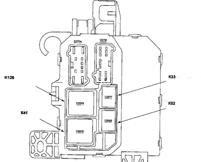
On the back of the unit there may be some relays, such as: K126 Anti-pinch relay, K41 Starter relay, K52 Relay Headlights, K33 Horn relay
In engine compartment
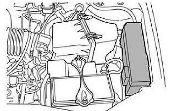
Fuse box located on the left side, next to the battery, under the protective cover. On the reverse side of which the actual assignment of fuses and relays will be applied.
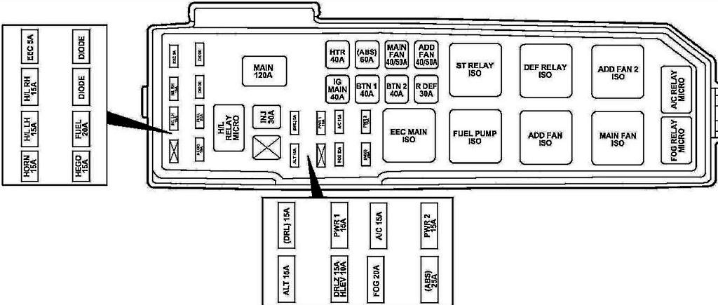
Type 1
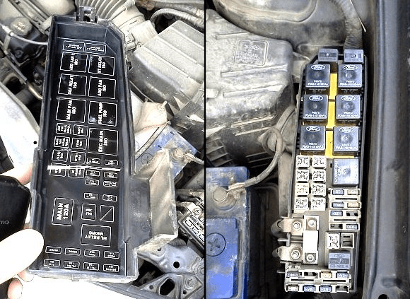
Photo - example.
| Diagram | |
|---|---|
|
|
| Name | Description |
| Horn | 15A Sound signal |
| H / LLH | 15A Left headlight |
| H / L RH | 15A Right headlight |
| EEC | 5A Engine management system |
| HEGO | 15A Fuel injection system |
| FUEL | 20A Fuel pump |
| DIODE | Diode |
| DIODE | Diode |
| H / L RELAY MICRO |
Headlight relay |
| INJ | 30A Engine management system, MAF sensor, idle speed control valve |
| MAIN | 120A Main fuse |
| ALT | 15A Generator |
| (DRL) | 15A Daytime lighting system |
| (DRLZ) | 15A Daytime lighting control unit |
| (HLEV) | 10A Headlight range control |
| PWR1 | 15A Socket for connecting additional devices |
| FOG | 20A Fog lights |
| A / C | 15A Air conditioning compressor clutch |
| (ABS) | 25A Anti-lock braking system |
| PWR2 | 15A Socket for connecting additional devices |
| IG MAIN | 40A Starter circuit |
| HTR | 40A Fan motor, fan motor relay |
| BTN 1 | 40A Radio, cigarette lighter, instrument cluster, electric mirrors |
| (ABS) | 60A ABS pump motor |
| BTN 2 | 40A Radio tape recorder, instrument cluster, "cruise control", power seat adjustment, sound signal |
| MAIN FAN | 40 / 50A Main fan |
| RDEF | 30A Heated rear door glass |
| ADD FAN | 40 / 50A Additional fan |
| EEC MAIN ISO |
Engine control relay |
| FUEL PUMP ISO |
Fuel pump relay |
| MAIN FAN ISO |
Low fan speed relay (YF motor) High fan speed relay # 1 (AJ motor) |
| ADD FAN ISO |
High fan speed relay (YF motor) Low fan speed relay (AJ motor) |
| DEF RELAY ISO |
Rear door glass heater relay |
| ST RELAY ISO |
Starter relay |
| ADD FAN 2 ISO |
Relay # 2 high fan speed (AJ engine)Relay for middle fan speed (YF motor) |
| FOG RELAY MICRO |
Fog lamp relay |
| A / C RELAY MICRO |
A / C compressor clutch relay |
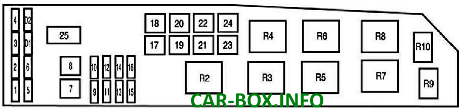
Type 2
Diagram.
|
|
| № | Appointment |
| 1 | 25A Instrument panel fuse |
| 2 | 25A Headlights |
| 3 | 25A High beam headlights, direction indicators, interior lighting, headlights |
| 4 | 5A Delay system for turning off the power of some circuits after turning off the ignition |
| 5 | 15A Oxygen sensor heater |
| 6 | 20A Gasoline pump |
| 7 | 40A RUN / ACC Relay - Cigarette Lighter, Windshield and Tailgate Wipers |
| 8 | 30A Engine and automatic transmission control unit, injectors and coils |
| 9 | 15A Generator |
| 10 | 30A Heated seats |
| 11 | 10A Engine and automatic transmission control unit |
| 12 | 20A Sockets for connecting additional equipment |
| 13 | 20A Fog lights (headlights / lights) |
| 14 | 15A A / C compressor magnetic clutch, A / C relay |
| 15 | 30A Anti-lock braking system |
| 16* | 25A Instrument panel fuse |
| 17 | 50A Starter circuit |
| 18 | 40A Fan motor |
| 19 | 40A Auxiliary relay - subwoofer, AWD system, low beam headlights |
| 20 | 60A Anti-lock braking system |
| 21 | 40A Horn, auxiliary brake light, instrument cluster, central locking and power seats |
| 22 | 40 / 50A radiator fan |
| 23 | 40A Heated rear door glass, parking light relay |
| 24 | 40 / 50A High / low speed fan |
| 25 | Shunt |
| R2 | Relay for engine and automatic transmission control unit |
| R3 | Fuel pump relay |
| R4 | Radiator fan relay |
| R5 | Relay # 1 high / low fan speed |
| R7 | Starter relay |
| R8 | Relay # 2 high / low fan speed |
| R9 | Fog lamp relay (headlights / lights) |
| R10 | Air conditioner relay |
| D1 | Starter diode |
| D2 | Air conditioner diode |
Type 3

General view.
| Diagram | |
|---|---|

|
|
| № | Appointment |
| A | 80A Electronic Power Steering (EPAS) Module |
| B | 125A Passenger compartment fuse panel |
| 1 | 15A Heated mirror |
| 2 | 30A Rear heater |
| 3 | 20A Rear sockets (center console) |
| 4 | Reserve |
| 5 | 10A Powertrain Control Module (PCM) - Supports Power, PCM Relay, Canister Vent |
| 6 | 15A Generator |
| 7 | 15A Moonroof |
| 8 | 20A Trailer parking lights |
| 9 | 50A Anti-lock braking system (ABS) |
| 10 | 30A Front wipers |
| 11 | 30A Starter |
| 12 | 40A Fan motor |
| 13 | 10A Air conditioner clutch |
| 14 | 15A Trailer headlights |
| 15 | Reserve |
| 16 | 40A Cooling fan 1 |
| 17 | 40A Cooling fan 2 |
| 18 | 20A ABS |
| 19 | 30A Power seats |
| 20 | Air conditioner drive relay |
| 21A | Rear defogger relay |
| 21B | Fuel relay |
| 21C | Fan relay |
| 21D | PCM relay |
| 22 | 20A Fuel pump |
| 23 | 15A Fuel injectors |
| 24 | Not used |
| 25 | 5A ABS |
| 26 | 15A Ignition coils |
| 27 | 10A control lamp of malfunction of power train components |
| 28 | 20A Power Train Component Malfunction Indicator Lamp |
| 29 | 15A PCM |
| 30A | Cooling fan relay 1 |
| 30B | Starter relay |
| 30C | Cooling Fan Main Relay |
| 30D | Cooling fan relay 2 |
| 31A | Tail light relay |
| 31B | Not used |
| 31C | Left Turn Trailer Relay |
| 31D | Trailer Right Turn Relay |
| 31E | Trailer |
| 31F | Lock relay |
| 32 | Not used |
| 33 | Air conditioner diode |
| 34 | Starter diode |
| 35 | Strat / stop, reversing lights, rear heater relay |
| 36 | Reserve |
