Renault Master - belongs to the series of light-duty vehicles. Over the years, the Renault Master has been delivered to markets with a variety of body styles, both standard and extended. Master modifications with increased payload are also known as Messenger and Mascott. This model represents a copy of Opel Movano and Nissan Interstar, they have a similar block arrangement. Renault Master of the 2nd generation was produced in 1997, 1998, 1999, 2000, 2001, 2002, 2003, 2004, 2005, 2006, 2007, 2008, 2009 and 2010. During this period, the car was restyled.

We will provide information on the location of relay and fuse blocks for 2nd generation, show photos of the blocks, a diagram and a description of their purpose. Let's highlight the fuse responsible for the cigarette lighter.
In the passenger compartment
Fuse box

The mounting block is located on the left side of the dashboard.
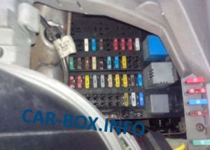
Depending on the configuration, there are several options for its execution.
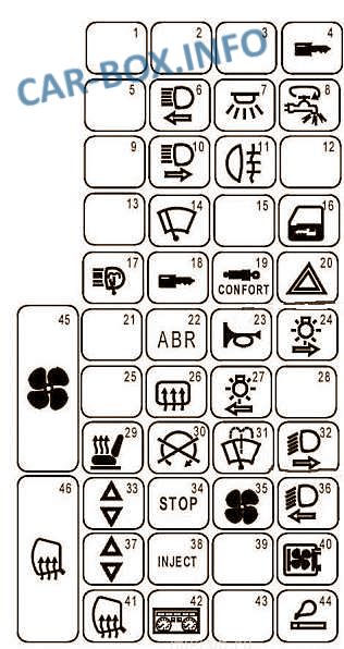
Type 1
General view.
| Diagram | ||
|---|---|---|
|
||
| No. | Description | Amps |
| 1 | Spare | - |
| 2 | Spare | - |
| 3 | Spare | - |
| 4 | Anti-theft device, Shock sensor | 20 |
| 5 | Spare | - |
| 6 | LH high beam headlamp, Instrument panel | 10 |
| 7 | Light, Audio system memory, Instrument panel, Remote control receiver for door locks, Interior lighting, Index with built-in clock, Door lock control relay, Tachograph | 15 |
| 8 | Fuse for deflection of electrical consumers | 30 |
| 9 | Spare | - |
| 10 | Right headlight (high beam) | 10 |
| 11 | Rear fog lamps, Instrument panel | 7.5 |
| 12 | Spare | - |
| 13 | Spare | - |
| 14 | Windshield wiper motor | 20 |
| 15 | Spare | - |
| 16 | Central locking system for door locks | 25 |
| 17 | headlight washer | 30 |
| 18 | OBD2 On-Board Diagnostic Connector | 2 |
| 19 | Air suspension | 5 |
| 20 | Alarm, Diagnostic connector | 15 |
| 21 | Spare | - |
| 22 | Anti-lock braking system (ABS) | 2 |
| 23 | Gudo | 15 |
| 24 | Right side light bulb, Lantern illuminated license plate | 7.5 |
| 25 | Spare | - |
| 26 | Heated rear window | 5 |
| 27 | Left side lamps, license plate lights, backlight lamps for control switches and cigarette lighter |
20 |
| 28 | Spare | |
| 29 | Seat heating | 15 |
| 30 | Diesel stop solenoid valve, Preheating system, Injection system. |
20 |
| 31 | Windshield wiper, washer | 15 |
| 32 | Right headlight (low beam) | 10 |
| 33 | Electric glass passenger door lifter | 25 |
| 34 | Brake lights, Reversing lights | 20 |
| 35 | Electric fan for air supply to the cab | 20 |
| 36 | Headlight washer timing relay, LH headlight (low beam), Instrument panel | 10 |
| 37 | Driver's door power window | 25 |
| 38 | Injection computer | 7.5 |
| 39 | Spare | - |
| 40 | Audio System, Tachometer Relay, Diesel Heater Relay | 20 |
| 41 | Heating elements for outside rear-view mirrors | 10 |
| 42 | Outdoor lighting not switched off indicator, Instrument panel | 15 |
| 43 | Spare | - |
| 44 | Renault Master cigarette lighter | 25 |
| 45 | Electric fan supplying air to the cab of the car with air conditioning | 40 |
| 46 | Heated rear window | 40 |
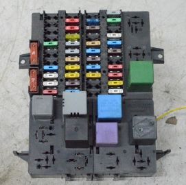
Type 2
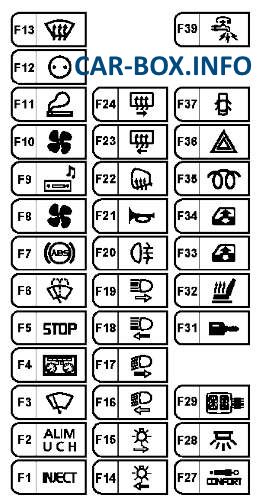
Diagram.
| No. | Decoding | Amps |
| F1 | Engine ECU, Starter Relay, Diagnostic Connector | 5 |
| F2 | UCH, first row cigarette lighter, central locking, heated rear window, idle speed control, rear fog light relay, air conditioning control panel, speed control, brake light switch, speed control, air suspension, headlight range control, heated windshield, Parking control ECU, speed controller, steering control ECU | 10 |
| F3 | wiper and washer switch, UCH | 30 |
| F4 | instrument panel, airbag ECU, tachograph | 15 |
| F5 | brake light switch, alternator, reversing light switch, reversing light relay | 15 |
| F6 | wiper and washer switch, windscreen wiper motor | 15 |
| F7 | ABS, vehicle speed sensor | 5 |
| F8 | Engine Cooling Fan Relay, A / C Compressor Relay, Diesel Heater Relay | 15 |
| F9 | audio system, multifunction display, radiotelephone interface, central communication unit | 10 |
| F10 | air conditioner control panel | 30 |
| F11 | Cigarette lighter Renault Master 2 | 10 |
| F12 | socket for additional equipment | 15 |
| F13 | Engine ECU relay | 5 |
| F14 | left side light, left tail light, left license plate light, caravan connector, UCH, audio system, multifunction display | 5 |
| F15 | right side light, left tail light, right license plate light, trailer connector, instrument panel | 5 |
| F16 | left headlight (low beam), headlight range control switch | 10 |
| F17 | right headlight (low beam) | 10 |
| F18 | left headlight (high beam), instrument panel | 10 |
| F19 | right headlight (high beam) | 10 |
| F20 | rear Fog lamps, connector for connecting a caravan | 10 |
| F21 | Horn | 15 |
| F22 | heated exterior mirrors | 5 |
| F23 | heated right rear window sidewall | 20 |
| F24 | heated left rear window sidewall | 20 |
| F25 | Not | |
| F26 | Not | |
| F27 | controlled suspension relay | 5 |
| F28 | tachograph, instrument panel, alarm siren, diagnostic socket, anti-theft alarm sensor | 15 |
| F29 | audio system, multifunction display, radiotelephone interface, central communication unit | 10 |
| F30 | Not | |
| F31 | shock sensor, UCH | 5 |
| F32 | heating elements for front seats, switch for outside rearview mirrors | 15 |
| F33 | driver's door power window switch, passenger door power window switch | 20 |
| F34 | window lifter time relay | 20 |
| F35 | diesel fuel heater | 20 |
| F36 | alarm switch | 15 |
| F37 | central locking switch | 30 |
| F38 | Not | |
| F39 | disconnection of electrical consumers (supply of fuses F27, F28, F29 and F31) | 30 |
Relay panel
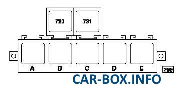
Diagram.
| No. | Component |
| A | Relay + after ignition 1 |
| B | Not |
| C | 4 speed of the interior fan |
| D | Switching off the auxiliary heater |
| E | Heated rear window and exterior mirrors |
In the engine compartment
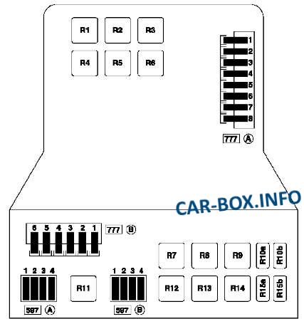
Fuse box

The mounting fuse box is on the left, near the rack.
| Diagram | ||
|---|---|---|
|
||
| No. | Description of board A (777) | Amps |
| 1 | passenger compartment fuse box power supply circuits, outdoor lighting and turn signal switch, ignition switch | 70 |
| 2 | air conditioner control panel | 30 |
| 3 | passenger compartment fuse box power supply circuit, turn signal exterior light switch | 70 |
| 4 | Not | |
| 5 | relay power circuit after ignition 1, rear window defogger relay, passenger compartment fuse box | 70 |
| 6 | air suspension relay | 30 |
| 7 | heated windscreen relay | 70 |
| 8 | ABS ECU power relay | 60 |
| No. | Decoding board B (777) | Amps |
| 1 | power supply circuit of the preheating unit | 70 |
| 2 | engine cooling fan 1, low speed cooling fan relay | 50 |
| 3 | Additional heating relay 1 | 30 |
| 4 | ZD3 engine: Cooling fan relay 2 | 40 |
| 5 | Additional heating relay 2 and 3 | 70 |
| 6 | transmission pump assembly relay | 30 |
| No. | Board A (597) | Amps |
| 1 | engine chain | 20 |
| 2 | fuel pump relay | 10 |
| 3 | Not | - |
| 4 | Injection computer | 25 |
| No. | Board B (597) | Amps |
| 1 | Additional heating relay 3/2/1 | 30 |
| 2 | 30 | |
| 3 | 30 | |
| 4 | contact plate power supply circuit for bodywork | 5 |
| No. | Relay modules | |
| R1 | Air suspension relay | |
| R2 | Running engine relay for G9T and G9U engines in 16-seat bus modification or for additional equipment | |
| R3 | Heated windshield relay | |
| R4 | Not | |
| R5 | ||
| R6 | ||
| R7 | Engine cooling fan relay 2 on vehicles with air conditioning | |
| R8 | Not | |
| R9 | Additional heating relay 3 | |
| R10a | Not | |
| R10b | Not | |
| R11 | Additional heating relay 2 | |
| R12 | Engine ECU relay | |
| R13 | Additional heating relay 1 | |
| R14 | Engine cooling fan relay 1 on vehicles with heating and air conditioning | |
| R15a | A / C compressor relay | |
| R15b | Diesel heater relay | |
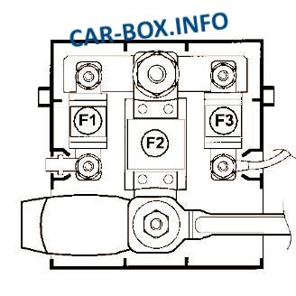
Power fuse panel
Located on the positive terminal of the battery.
| Diagram | ||
|---|---|---|
|
||
| No. | Description | Amps |
| F1 | Cabin fuse box | 40 |
| F2 | Power supply for the power circuit fuse box, starter, starting system | 400 |
| F3 | injection computer power relay | 40 |
