H-1 Grand Starex is a LCV/minivan of a wide range of applications (due to the variety of modifications offered by the manufacturer) of the Korean concern Hyundai Motor Company. The first generation of the car started to be produced in 1996, currently the second generation H-1 is being produced, presented in 2007. In this article, we will take a detailed look at the fuse box diagrams for the Hyundai Grand Starex / H1 (second generation; TQ index) 2007, 2008, 2009, 2009, 2010, 2010, 2011, 2012, 2013, 2014, 2014, 2015, 2016, 2016, 2017, 2018, 2018, 2019, 2020, 2021, 2022 years of manufacture.

Here you will find the locations and photos of distribution boxes. The fuses responsible for the “Cigarette lighter” and “Fuel Pump” are highlighted in bold.
In the engine compartment
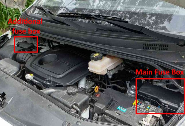
Location of underhood units.
Main fuse box
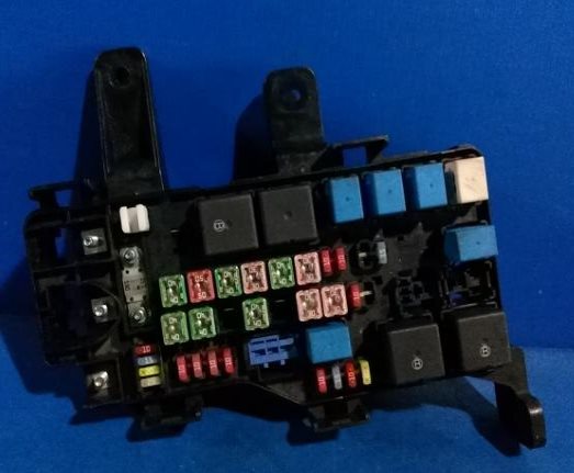
Located on the left side of the engine compartment, next to the battery.
| Diagram | ||
|---|---|---|

|
||
| Name | Amps / Description | A |
| ALT | Fuse (A / CON, FRT DEICER), fuse (FRT HTR, RR HTR, RR HTD, C / FAN, F / FILTER, ABS 1/2), alternator, E / R fuse and relay box, right | 150 |
| BATT1 | Fuse (DR LOCK, FRT FOG LP, B / ALARM, power connector (AUDIO-1, ROOM LP)) | 50 |
| BATT2 | Fuse (FUEL LID, P / WDW LH / RH, HAZARD), multipurpose test connector | 30 |
| BATT 3 / RAD FAN | Fuse (STOP LP, BWS), radiator fan relay (G4KC) | 40 |
| IGN 1 | Ignition switch (ACC, IG1) | 40 |
| IGN 2 | Ignition switch (IG2, START), start relay | 40 |
| ECU MAIN | Engine control relay | 20 / 30 |
| FRT HTR | Front fan relay | 40 |
| RR HTD | Rear window defogger relay | 40 |
| RR HTR | Rear fan relay | 40 |
| ABS 1 | ABS Control Module (G4KC) | 40 |
| ABS 2 | ABS Control Module (G4KC) | 40 |
| C / FAN | Condenser fan relay 1 | 30 |
| F / FILTER | Fuel filter heater relay (DIESEL) | 30 |
| 1 | TCM, ECM (petrol) | 10 |
| 2 | Horn relay | 10 |
| 3 | Fuel heater control module (D4CB) | 20 |
| Fuel pump relay (G4KC) | 15 | |
| Alternator (D4BH) | 10 | |
| 4 | Headlight relay (HIGH), headlight relay (LOW) | 15 |
| 5 | Air conditioner relay | 10 |
| FRT DEICER | Windshield heater relay (if equipped) | 15 |
| 7 | Left headlight (side light), left rear combination light, left side light | 10 |
| 8 | Headlight right (side light), rear combination light right, side light right | 10 |
| 9 | Headlight, left | 10 |
| 10 | Headlight, right | 10 |
| 11 | A / C relay, condenser fan relay (D4CB), lambda probe (D4CB), heater # 1 PTC relay (D4CB), brake light switch (D4CB) | 10 |
| 12 | D4CB: camshaft position sensor, glow plug relay, EGR actuator, VGT control valve, immobilizer control module G4KC: fuel pump relay, canister purge solenoid valve, oil control valve, crankshaft position sensor, oxygen sensor, immobilizer control module, idle speed control actuator | 15 |
| 13 | Ignition coil # 1 ~ # 4 (G4KC), capacitor (G4KC) | 15 |
| ECU (D4CB) | 10 | |
| 14 | ECM (D4CB, G4KC), injector # 1 ~ # 4 (G4KC) | 20 |
| SAFETY P / WDW | Power Window Safety Lift | 20 |
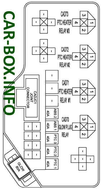
Additional distribution box
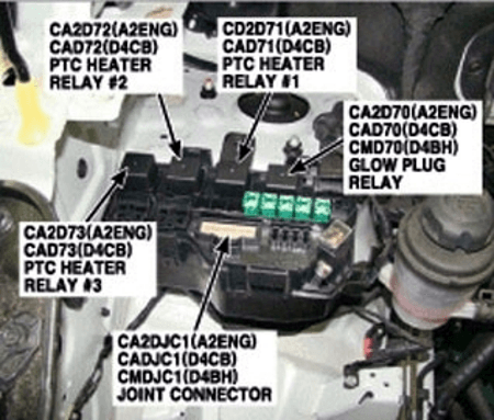
Installed mainly on diesel models, on the right side, next to the rack.
| Diagram | ||
|---|---|---|
| Type 1 | ||
|
||
| Name | Description | Amps |
| GLOW | Glow plug relay | 80 |
| PTC HEATER 1 | PTC heater relay # 1 | 40 |
| PTC HEATER 2 | PTC heater relay # 2 | 40 |
| PTC HEATER 3 | PTC heater relay # 3 | 40 |
| ABS 1 | ABS / ESC control unit | 40 |
| ABS 2 | ABS / ESC control unit | 40 |
| ECU | Power supply to the electronic control unit | 15 |
| FUEL PUMP | Fuel pump fuse | 20 |
| DCU 1 | Dispense control unit power supply 1 | 20 |
| DCU 2 | Dispense control unit - Power supply 2 | 20 |
| DCU 3 | Dispense control unit - Power supply 3 | 20 |
| DCU | Main power supply for batch control unit | 30 |
| Type 2 | ||

|
||
In the passenger compartment
There are two units responsible for protecting the vehicle's electrical circuits.
Main fuse box

Located at the bottom of the dashboard (driver's side), behind the cover.
Type 1

General view of the Hyundai Grand Starex / H1 interior fuse box.
| Diagram | ||
|---|---|---|
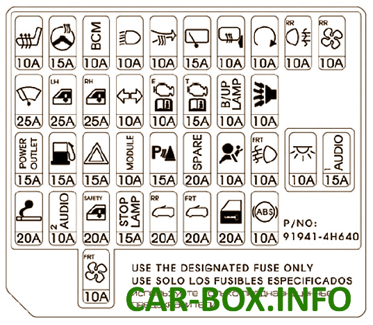
|
||
| Name | Description | A |
| AUDIO-2 | Audio system, digital clock, BCM, external electric mirror switch | 10 |
| C / LIGHTER | Cigarette Lighter, Front Socket | 20 |
| S / HTD DRI | Driver's seat heating switch (if fitted) | 10 |
| DRL | BCM - daytime running lights (if fitted) | 10 |
| RR FOG LP | Rear fog light relay | 10 |
| H / LP | Relay high / low beam headlights | 10 |
| FRT WIPER | Front wiper relay, front wiper motor | 25 |
| BCM | Body control module | 10 |
| HTR | Front/rear fan relay, front/rear A/C control module, condenser fan relay, electrochromic mirror, thermal switch, PTC heater relay (D4CB), EGR solenoid valve (D4BH) | 10 |
| B / UP LP | Reverse light relay, reverse light switch, transmission range switch | 10 |
| ABS | ABS / ESP control unit, ESP switch (D4CB) | 40 |
| T / SIG LP | Turn signal switch | 10 |
| A / BAG | SRS control module | 10 |
| A / BAG IND | Instrument cluster (indication) | 10 |
| MODULE | Dashboard, BCM, immobilizer control module (D4BH), air conditioning relay (D4BH), alternator resistance | 10 |
| ECU | Vehicle speed sensor, ECM, air flow sensor (D4CB), fuel pump (D4BH), TCM, fuel filter warning sensor | 10 |
| START | Start Relay, Burglar Alarm Relay | 10 |
| MIRR HTD | Front A/C control module, power outside mirror and heated left/right window | 10 |
| STOP LP | Brake light switch | 15 |
| BWS | Buzzer | 10 |
| DR LOCK | Door lock / unlock relay | 20 |
| FRT FOG LP | Front fog lamp relay | 10 |
| B / ALARM | Alarm horn relay | 10 |
| AUDIO-1 (POWER CONNECTOR) | Audio | 15 |
| ROOM LP (POWER CONNECTOR) | Digital clock, instrument cluster, LH/RH lighting, LH/RH footrest, luggage compartment lamp, interior light switch, door alarm switch, data connector, BCM, LH/RH vanity light switch, overhead console lighting | 10 |
| HAZARD | Alarm relay, emergency switch | 15 |
| FUEL LID | Fuel filler flap relay | 15 |
| P / WDW LH | Main switch for power windows, left power window switch | 25 |
| P / WDW RH | Main switch for power windows, right power window switch | 25 |
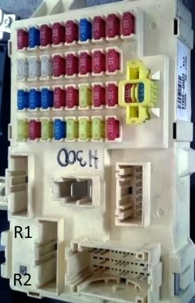
Relay decoding
- R1 - power windows relay
- R2 - filler flap relay
The following non-removable relays can also be mounted on the reverse side:
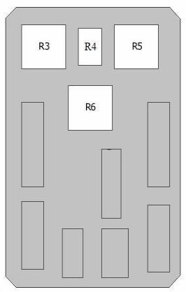
- R3 - Rear blower;
- R4 - Rear lights;
- R5 - Front blower;
- R6 - Rear demister.
Type 2
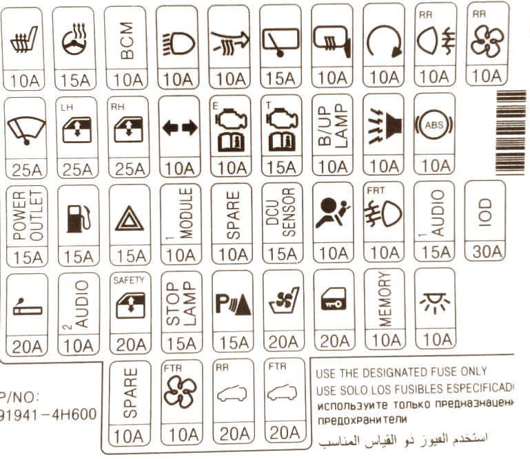
Diagram.
Additional box
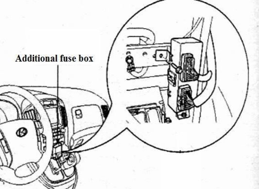
Location.
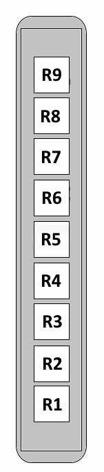
Integrated circuit module (ICM):
- R1 – Rear fog light;
- R2 – Front fog light;
- R3 – Flasher unit;
- R4 – Hazard warning light or not used;
- R5 – Security alarm system;
- R6 – Security system horn;
- R7 – Rear wiper;
- R8 – Door lock;
- R9 – Door unlock.
