The i20 is a supermini hatchback produced by Hyundai since 2008. The model made its debut at the Paris Motor Show in October 2008 and is positioned between the i10 and i30 models. In this article, we will take a detailed look at the fuse box diagrams for the Hyundai i20 (first and second generation; PB / GB index) 2008, 2009, 2009, 2010, 2011, 2011, 2012, 2013, 2014, 2015, 2015, 2016, 2017, 2017, 2018, 2019, 2020, 2021 years of manufacture.
Here you will find the locations and photos of distribution boxes. The fuses responsible for the “Cigarette lighter” and “Fuel Pump” are highlighted in bold.
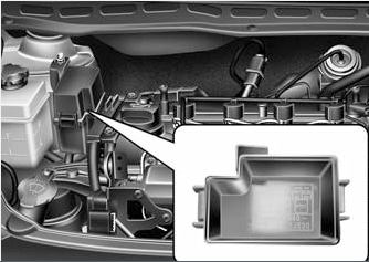
In the engine compartment

Location of underhood units.
Main fuse box

Located on the left side of the engine compartment, next to the battery.
Type 1

General view.
| Diagram | |
|---|---|

|
|
| Name | Description |
| BATT 2 | Instrument panel junction box (relay for electric drive glass lifters, fuses (SAFETY P / W - 15 A, HAZARD - 15 A)) |
| BATT 1 | Instrument Panel Junction Box (Tail Lamp Relays, Fuses (S / ROOF - 20 A, FOLDING - 10 A, DR LOCK - 20 A, STOP LP - 15 A, V / A HORN - 15 A, RR FOG LP - 10 A , FRT FOG LP - 10 A, power connector (ROOM - 10 A, AUDIO - 20 A)) |
| C / FAN | High speed cooling fan relay, low speed cooling fan relay |
| MAIN | Alternator, fuses (ABS 1 - 40 A. ABS 2 - 40 A, RR HTD - 40 A, BLOWER - 40 A, MDPS - 80 A, A / CON 1 - 10 A) |
| ABS2 | Multipurpose test connector, anti-lock brake system (ABS) control unit, electronic stability control (ESP) control unit |
| ABS 1 | Multipurpose test connector, anti-lock brake system (ABS) control unit, electronic stability control (ESP) control unit |
| RR HTD | Rear heating relay |
| BLOWER | Fan relay |
| MDPS | Electronic stability control (ESP) control unit |
| IGN 2 | Ignition |
| ECU A | Engine control module (ECM) (with manual transmission), transmission control module (PCM) (with automatic transmission), engine control relay (main relay) |
| F / PUMP | Hyundai i20 fuel pump fuse |
| IGN 1 | Egnition lock |
| HORN | Horn relay |
| SNSR 1 | Camshaft position sensor, fuel vapor storage purge control solenoid valve, oxygen sensor (upper, lower), immobilizer control unit, cooling fan low speed relay, cooling fan high speed relay |
| ECU B | Engine Control Module (ECM) (with manual transmission), Transmission Control Module (PCM) (with automatic transmission) |
| DRL | Ground (body electronic control module (BCM)) |
| ECU 1 | Engine Control Module (ECM) (with manual transmission), Transmission Control Module (PCM) (with automatic transmission) |
| INJ | Injectors 1-4, idle speed control actuator, air conditioning relay, oil flow control valve (GAMMA) |
| A / CON2 | Air conditioner control unit |
| A / CON 1 | Air conditioner relay |
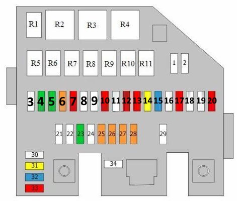
Type 2

General view.
| Diagram | ||
|---|---|---|
|
||
| № | Decrtiption | Amps |
| 1 | Empty | - |
| 2 | Empty | - |
| 3 | Ignition switch | 50 |
| 4 | Engine control relay | 30 |
| 5 | Fuel filter heater relay | 30 |
| 6 | Ignition switch | 40 |
| 7 | Horn relay | 10 |
| 8 | Empty | - |
| 9 | Empty | - |
| 10 | Oxygen sensor, Brake light switch, Air heater, Cooling fan, low speed relay / Cooling fan, high speed relay | 10 |
| 11 | Empty | - |
| 12 | Ground | 10 |
| 13 | Fuel pressure regulator | 10 |
| 14 | Engine control unit | 20 |
| 15 | EGR, immobilizer control unit, engine compartment fuse and relay box, relays R1, R4, air conditioning relay, variable geometry turbine (VGT), camshaft position sensor | 15 |
| 16 | Empty | - |
| 17 | Air-conditioning control unit | 10 |
| 18 | Empty | - |
| 19 | Empty | - |
| 20 | Air-conditioning relay | 10 |
| 21 | Fuse and relay box in passenger compartment, relay R2 and fuses 21, 22 | 50 |
| 22 | Fuse and relay box in passenger compartment, relay R8 and fuses 2 – 7, 25, 33, 34 | 50 |
| 23 | Cooling fan, high-speed relay / Cooling fan, low-speed relay | 30 |
| 24 | Fuse and relay box in engine compartment, fuses 20, 25 – 29, 34, Generator | 125 |
| 25 | ESP control unit, Multi-purpose check connector, ABS control unit | 40 |
| 26 | ESP control unit, Multi-purpose check connector, ABS control unit | 40 |
| 27 | Rear heater relay | 40 |
| 28 | Blower relay | 40 |
| 29 | EPS control unit | 80 |
| 30 | Spare | 25 |
| 31 | Spare | 20 |
| 32 | Spare | 15 |
| 33 | Spare | 10 |
| 34 | Fuse and relay box No. 1 in engine compartment, relays R1 – R4 | 150 |
| R1 | Empty | |
| R2 | Blower relay | |
| R3 | Fuel filter heater | |
| R4 | Engine control unit | |
| R5 | Daylight running system relay | |
| R6 | Air-conditioning relay | |
| R7 | Starter relay | |
| R8 | Security alarm system relay | |
| R9 | Horn relay | |
| R10 | Cooling fan, low-speed relay | |
| R11 | Cooling fan, high-speed relay | |
Additional distribution box
Fits on the right side of the engine compartment on i20 diesel models.

Desctiption:
- R1 - Glow plug relay;
- R2 - PTC, relay 3;
- R3 - PTC, relay 2;
- R4 - PTC, relay 1;
- 1 - PTC relay 3 50A;
- 2 - PTC relay 2 50A;
- 3 - PTC relay 1 50A;
- 4 - Glow plug relay / Air heating 80A.
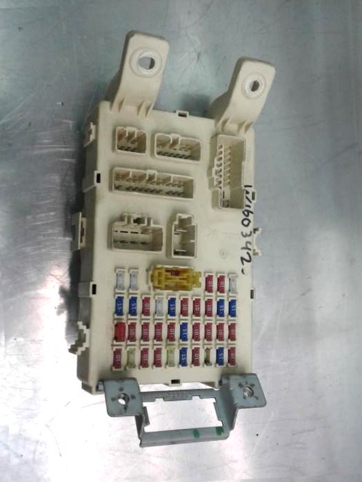
In the passenger compartment
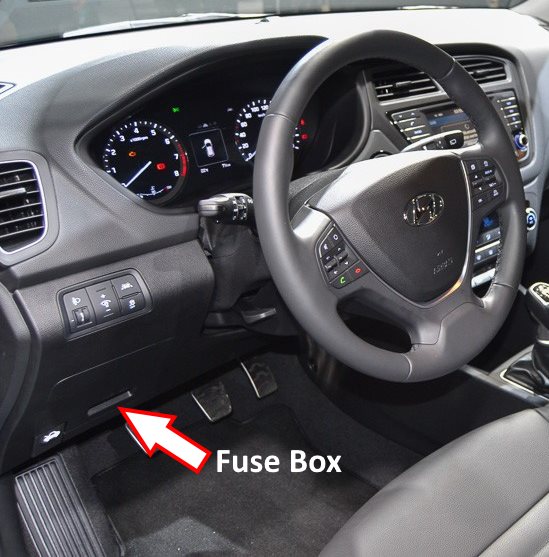
Located at the bottom of the dashboard.
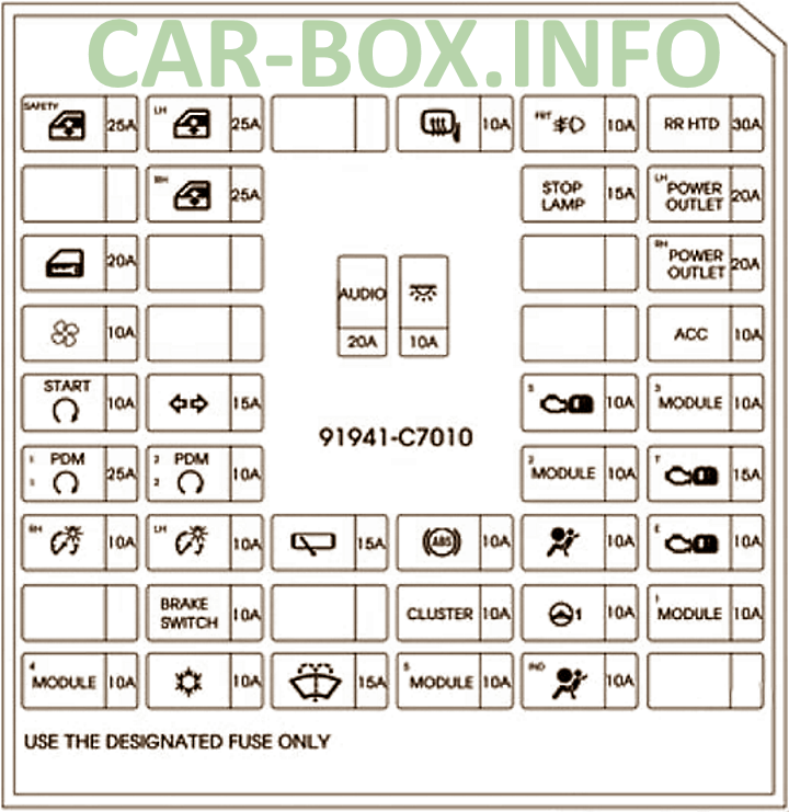
Type 1
First version of the unit.
| Diagram | |
|---|---|
|
|
| Name | Descripion |
| P / WDW -LH | Power window main switch, driver's door power window automatic interlock assembly, right rear door glass control switch, front passenger door glass control switch (for right-hand drive vehicles) |
| S / HTD | Front passenger seat heating switch, driver's seat heating switch |
| RR WIPER | Rear window wiper motor, multifunction switch (wiper control switch) |
| H / LP RH | Headlight right, dashboard (headlights on) |
| IGN 2 | Headlight leveling switch, cabin temperature sensor, electronic body control module (BCM), air conditioning control module, sunroof control module, left/right headlights, engine compartment fuse and relay box (fuel filter heater relay (FFHS), daytime running light relay (DRL), blower relay), diesel fuse/relay box (heater relay PTC 2, heater relay PTC 3) |
| PCU | Fuel filter warning sensor, air flow sensor, engine control module (ECM) (with manual transmission), transmission control module (PCM) (with automatic transmission) |
| STOP LP | Brake Light Switch, Data Link Connector (DLC), Power Window Relay |
| A / BAG | Seat Belt Not Fastened Sensor Module, SRS Control Module |
| HAZARD | Alarm switch, alarm relay |
| SAFETY P / W | Automatic blocking block of the electric drive glass of the driver's door lift |
| CLUSTER | On-board computer, instrument panel (backlight), body electronic control module (BCM) |
| TCU | Overdrive switch, pulse generator “A”, pulse generator “B”, vehicle speed sensor |
| IGN1 | Alternator (KAPPA), Electric Power Steering (EPS) Control Unit, Tire Pressure Monitor |
| ABS | Electronic stability system (ESP) switch, steering angle sensor, anti-lock brake system (ABS) control unit, ESP control unit, yaw angle sensor, engine compartment fuse and relay box (multi-purpose test connector) |
| IGN COIL | Ignition coil (KAPPA), ignition coils Nos. 1 - 4 (GAMMA), capacitor (GAMMA) |
| B / UP LP | Transmission mode switch (GAMMA), reversing lamp switch |
| A / BAG IND | Dashboard (airbag lighting) |
| T / SIG LP | Hazard switch |
| TAIL LP LH | Daytime running light relay (DRL), license plate light, left rear combination light, left headlight |
| TAIL LP RH | Headlight right, right rear combination lamp, lighting |
| ACC | Electric drive of outside rear-view mirrors, audio system, on-board computer |
| C / LIGHT | Hyundai i20 cigarette lighter fuse |
| RR FOG LP | Rear fog lamp relay |
| B / A HORN | Anti-theft alarm relay |
| DR LOCK | Tailgate unlock relay, door lock / unlock relay, full door lock relay |
| FRT FOG LP | Front fog lamp relay |
| FOLDING | Power outside rearview mirror control switch |
| S / ROOF | Sunroof control unit |
| START | Engine Control Module (ECM) (for diesel vehicles), engine compartment fuse box and relays (starter relay, anti-theft alarm relay) |
Type 2
General view of the Hyundai i20 interior fuse box.
| Diagram | ||
|---|---|---|

|
||
| № | Description | Amps |
| R1 | Rear heater relay | |
| R2 | Power window relay | |
| R3 | Front fog light relay | |
| R4 | Rear fog light relay | |
| R5 | Empty | |
| R6 | Door unlock relay / Door lock relay | |
| R7 | Tailgate unlocking relay / Tailgate lock relay | |
| R8 | Tail light relay | |
| R9 | Daylight running system relay | |
| R10 | Hazard warning light relay | |
| 1 | Fuse and relay box in engine compartment (relays R7, R8), Engine control unit or not used | 10 |
| 2 | Sunroof control unit | 20 |
| 3 | Folding/unfolding function of exterior mirrors | 10 |
| 4 | Front fog light relay | 10 |
| 5 | Door lock relay, door lock relay, door unlock relay, tailgate unlock relay | 20 |
| 6 | Relay of the alarm system | 15 |
| 7 | Rear fog light relay | 10 |
| 8 | Not used | 25 |
| 9 | Cigarette lighter fuse | 15 |
| 10 | Audio, Trip computer, Electric mirrors | 10 |
| 11 | Lighting, right headlamp, rear combination lamp(s) | 10 |
| 12 | License plate light, Rear left combination light, Left headlight, Daylight running system relay | 10 |
| 13 | Hazard warning switch | 10 |
| 14 | Instrument panel | 10 |
| 15 | Rear light switch, transmission range selector switch | 10 |
| 16 | Condenser, Ignition coils 1 – 4 | 15 |
| 17 | Fuse and relay box in engine compartment (diagnostic connector), ESP control unit, Electronic stability program (ESP) switch, Steering angle sensor, Yaw rate sensor, ABS control unit | 10 |
| 18 | EPS Control Unit, Tire Pressure Monitoring System Control Unit, Generator | 10 |
| 19 | Pulse generator, Vehicle speed sensor, Overdrive main switch | 10 |
| 20 | Instrument panel, trip computer, body control module (BCM) | 10 |
| 21 | Driver’s power window | 15 |
| 22 | Hazard warning light relay, Hazard warning switch | 15 |
| 23 | SRS control unit, Seat belt switch | 10 |
| 24 | Not used | 25 |
| 25 | Data link connector, Power window relay, Brake light switch | 15 |
| 26 | Mass air flow meter, engine control unit, powertrain control module (PCM), fuel filter warning | 10 |
| 27 | Fuse box No. 1 in engine compartment, relays R2, R3, Fuse and relay box in engine compartment, relays R2, R3, R5, Air-conditioning control unit, Headlights, Sunroof control unit, Body control unit (BCM), In-car temperature sensor, Headlight levelling switch | 10 |
| 28 | Instrument panel, Right headlight | 10 |
| 29 | Multifunction switch, Rear wiper motor | 15 |
| 30 | Heated front seat(s) switch | 15 |
| 31 | Driver's power window, Rear left power window switch, Passenger power window switch (right-hand drive), Power windows, main switch | 25 |
| 32 | Driver’s power window, Switch, rear right power window(s), Passenger’s power window switch (left-hand drive), Power windows, main switch | 25 |
| 33 | Open door, instrument panel, trip computer, air conditioner control unit, luggage compartment lighting, overhead console, front interior lamps, interior lighting, rear heater relay, tire pressure monitoring system control unit, body control module (BCM) | 10 |
| 34 | Audio | 20 |
| 35 | Left headlight | 10 |
| 36 | Powertrain control unit (PCM), Air-conditioning control unit, Electric mirrors, Engine control unit | 10 |
| 37 | Multifunction switch, Front wiper motor | 25 |
