Matrix is a subcompact van of the Korean company Hyundai. In Japan, South Korea and Taiwan it was sold as Lavita, in Australia as Elantra Lavita, in Malaysia as Inokom Matrix. In this article, we will take a detailed look at the fuse box diagrams for the Hyundai Matrix / Lavita (first generation; FC index) 2001, 2002, 2003, 2003, 2004, 2004, 2005, 2006, 2007, 2008, 2009 and 2010 years of manufacture.
Here you will find the locations and photos of distribution boxes. The fuses responsible for the “Cigarette lighter” and “Fuel Pump” are highlighted in bold.
In the engine compartment
Depending on the type of engine installed (diesel or gasoline), there can be either one or two units.
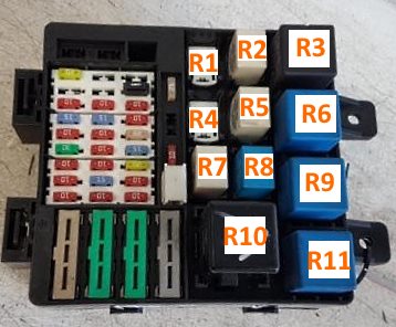
Primary fuse box
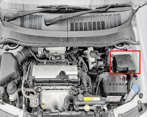
It is located next to the battery, under the protective cover.
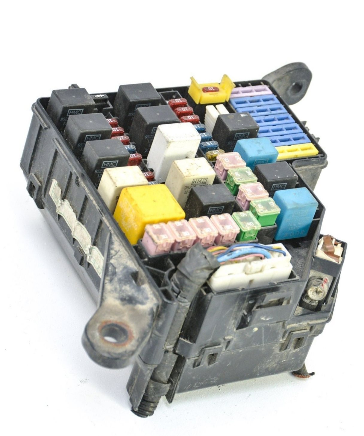
General view.
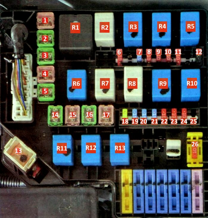
| Diagram | ||
|---|---|---|
|
||
| № | Description | Amps |
| 1 | COND - Electro condenser fan | 30 |
| 2 | ABS - ESP and anti-lock brakes ABS | 40 |
| 3 | ABS - ESP and anti-lock brakes ABS | 40 |
| 4 | P / WIN - power windows | 30 |
| 5 | BLR - Electric heater radiator fan | 40 |
| 6 | ABS - Anti lock brake system ABS | 10 |
| 7 | INJ - Fuel injectors, ignition coils | 15 |
| 8 | SNSR - Sensors of the engine management system | 10 |
| 9 | F / PUMP - Fuel pump fuse | 10 |
| 10 | TAIL LH - Left tail light, left license plate light | 10 |
| 11 | TAIL RH Right tail light, right license plate light | 10 |
| 12 | Rear fog lamp activation diode | |
| 13 | BATT - Generator | 120 |
| 14 | B + - Air conditioning, heated rear window, brake lights, central locking, anti-theft alarm system | 40 |
| 15 | ECU - engine control unit, alternator, main relay of the engine control system | 30 |
| 16 | IGN - Starter, ignition switch (lock) | 40 |
| 17 | RAD - Electro radiator fan | 30 |
| 18 | TAIL - Rear lights | 20 |
| 19 | FR FOG - Fog lights | 15 |
| 20 | H / LP LH - Left headlight | 15 |
| 21 | NDR RH - Right headlight | 15 |
| 22 | ECU - engine control unit, alternator, main relay of the engine control system | 10 |
| 23 | HORN - Sound signal | 10 |
| 24 | A / CON - Air conditioner | 10 |
| 25 | DRL - Side light control unit | 15 |
| 26 | ROOM LP - Car radio, interior lighting, dashboard illumination | 10 |
| R1 | MAIN - Main relay | - |
| R2 | COND2 - Condenser electric fan relay (low speed) | - |
| R3 | F / P CHK - Fuel pump relay | - |
| R4 | RAD - Relay, electric radiator fan | - |
| R5 | H / LP - Headlight relay | - |
| R6 | HORN - Horn relay | - |
| R7 | WIPER - Wiper relay | - |
| R8 | R / W DIODE - Relay for diode activation (pos. 12) | - |
| R9 | START - Starter relay | - |
| R10 | A / CON - Air conditioner relay | - |
| R11 | TAIL - Rear lamp relay | - |
| R12 | COND1 - Condenser electric fan relay (high speed) | - |
| R13 | FR FOG - Rear fog lamp switch relay | - |
Additional distribution box
Installed on models with a diesel engine.
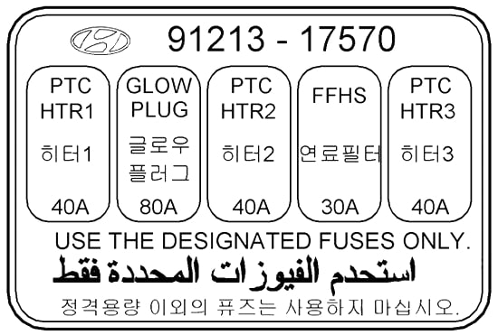
Description: GLOW PLUG; PTC - additional heater
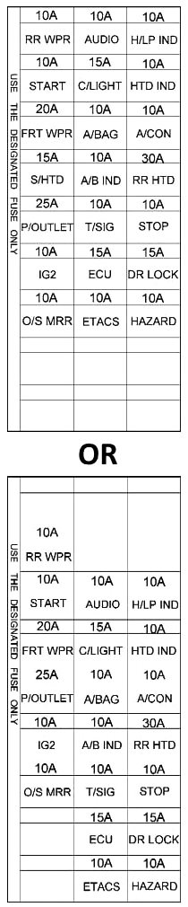
In the passenger compartment
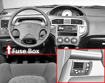
Located at the bottom of the dashboard.
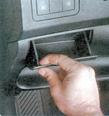
Remove the protective cover to access it.
| Relays | |
|---|---|
|
|
| № | Description |
| R1 | Reserve |
| R2 | Central locking relay (unlocked) |
| R3 | Alarm relay |
| R4 | Reserve |
| R5 | Central locking relay |
| R6 | Power window relay |
| R7 | Anti-theft relay |
| R8 | Anti-theft alarm siren relay |
| R9 | Heated rear window relay |
| R10 | Turn signal interrupter relay |
| R11 | Heater blower motor relay |
| Diagram | ||
|---|---|---|
|
||
| Name | Description | A |
| RR HTD | Rear window defogger relay | 30 |
| STOP | Brake light relay, power window relay | 10 |
| D / LOCK | Door lock (unlock) relay, ETASM, sunroof relay | 15 |
| HAZARD | Burglar alarm relay, alarm relay | 10 |
| AUDIO | Car radio | 10 |
| C / LIGHT | Hyundai Matrix Cigarette lighter fuse | 15 |
| A / B | Airbag control unit | 10 |
| A / B IND | Airbag warning lamp | 10 |
| T / SIG | Alarm switch, seat belt timer, instrument panel, ABS control unit, excitation resistor, washer pump actuator | 10 |
| ECU | ECM, vehicle speed sensor, TCM, ignition coil | 15 |
| ETACS | automatic transmission selector | 10 |
| RRWPR | Rear wiper motor, rear wiper relay | 10 |
| START | Starter relay | 10 |
| FRTWPR | Wiper relay, washer pump motor, wiper and rear window defroster timer | 20 |
| S / HTD | Switch for heating the left (right) front seat | 15 |
| P / OUTLET | Front (rear) socket for connecting external consumers | 25 |
| IG2 | ETASM, power window relay, rear wiper relay, sunroof relay, headlight relay, heating and air conditioning fan relay | 10 |
| O / S MRR | Exterior mirror switch, rear fog lamp relay | 10 |
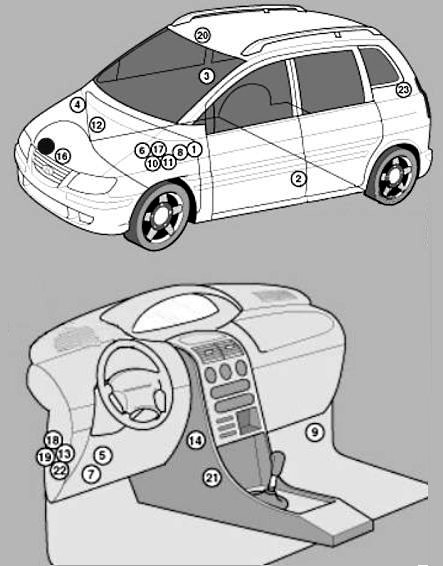
General arrangement
Location of electronic control units.
|
|
| 1 | ABS electronic control unit |
| 2 | Side impact sensor, left - B-pillar |
| 3 | Side impact sensor, right - B-pillar |
| 4 | Anti-theft alarm siren - partition |
| 5 | Audible Warning / Buzzer - Behind the dash fuse / relay box |
| 6 | Battery |
| 7 | Diagnostic connector (DLC) - under the dash |
| 8 | Daylight Control Module - Inner Wing |
| 9 | Electronic engine control unit - lower protection panel |
| 10 | Fuse / relay box, engine compartment 1 |
| 11 | Fuse / relay box, engine compartment 2 (Diesel) |
| 12 | Fuse / Relay Box, Engine Compartment W (Diesel) |
| 13 | Fuse / relay box, instrument panel |
| 14 | Heater fan motor resistor - next to the heater fan motor |
| 15 | Horn (top) |
| 16 | Horn (bottom) |
| 17 | Inertia Fuel Cut-Off Switch - Behind Battery |
| 18 | Immobilizer control unit - behind the dashboard fuse / relay box |
| 19 | Multifunction control unit - behind instrument panel fuse box / relay box - Anti-theft functions, central locking, heated rear window, ignition key buzzer, interior lighting / delayed switch-off, seatbelt warning system, windscreen wiper / washer |
| 20 | Sunroof Motor Relay - Headlining |
| 21 | Electronic control unit SRS - under the center console |
| 22 | Electronic control unit for gearbox - automatic transmission - behind the dashboard, on the left |
| 23 | Rear Wiper Relay - Luggage Compartment LH |
