Table of Contents
In this article, we will take a detailed look at the fuse diagrams for the car Lifan MyWay X70: 2016, 2017, 2018, 2019, 2020, 2021, 2022 of release.

Fuse number 27 in the passenger compartment is responsible for the cigarette lighter sockets.
In the passenger compartment
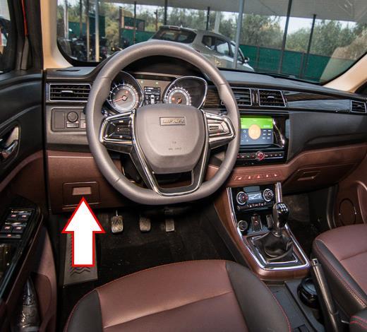
The distribution box is located behind the glove box on the driver's side.
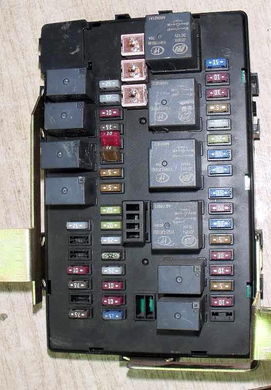
The photo shows an example.
| Diagram | ||
|---|---|---|
|
||
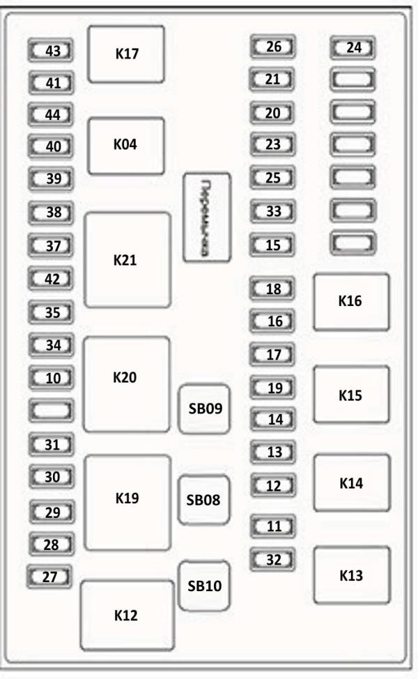
| No. | Relay assignment | |
| K04 | Daytime Running Lights | |
| K12 | heater fan | |
| K13 | Rear window heating | |
| K14 | Marker lamps | |
| K15 | Rear fog lights | |
| K16 | Front fog lights | |
| K17 | P/R relay | |
| K19 | ACC | |
| K20 | IG2 | |
| No. | Amps | Purpose of the fuses |
| 10 | 15 | Seat heating |
| 11 | 25 | Rear window heating |
| 12 | 10 | side light lamps |
| 13 | 7.5 | Rear fog lights |
| 14 | 10 | Front fog lights |
| 15 | 20 | Passive Keyless Entry/Engine Start System (PEPS) |
| 16 | 5 | Ignition Switch / Start Button Engine START-STOP |
| 17 | 5 | Engine Control Module (ECM) |
| 18 | 20 | Body electronics module (BCM) |
| 19 | 7.5 | Central locking circuit |
| 20 | 10 | Instrument Cluster / Diagnostic Connector (OBDII) |
| 21 | 10 | MP5 multimedia system |
| 23 | 10 | Sunroof |
| 24 | 7.5 | Stop lamps |
| 25 | 5 | Lamps for interior lighting, trunk, doors |
| 26 | 15 | In-Vehicle Emergency Call System (GLONASS) |
| 27 | 15 | Lifan MyWay cigarette lighter fuse |
| 28 | 10 | Additional socket 12V 120 W |
| 29 | 10 | Multimedia system MP5 |
| 30 | 5 | Power door mirrors / body electronics module (BCM) |
| 31 | 25 | Windshield wipers and washers |
| 32 | 25 | Front power windows |
| 33 | 25 | Rear power windows |
| 34 | 15 | Air conditioning control unit |
| 35 | 15 | Engine Control Module (ECM) |
| 37 | 15 | Instrument Cluster / Sunroof / Diagnostic Connector (OBDII) |
| 38 | 5 | Anti-lock braking system (ABS) |
| 39 | 10 | Electric Power Steering (EPS) |
| 40 | 10 | Airbags (SRS) |
| 41 | 10 | Daytime running lamps |
| 42 | 10 | Body electronics module (BCM) |
| 43 | 10 | AT |
| 44 | 5 | Passive Keyless Entry/Start System (PEPS) |
| SB08 | 30 | Power supply IG2/ACC |
| SB09 | 30 | Power supply IG1 |
| SB10 | 30 | Main heater fan |
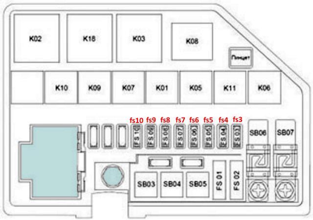
In the engine compartment
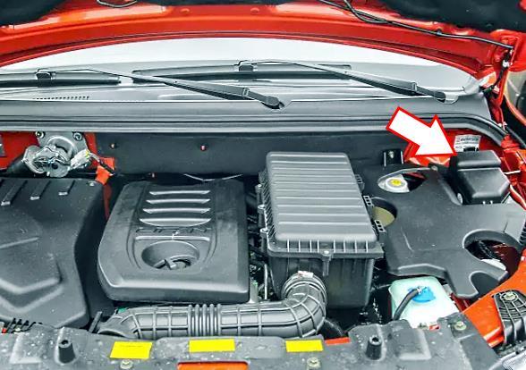
The fuse box is located on the right side of the engine compartment. To access it, you need to open the protective cover.
| Diagram | ||
|---|---|---|
|
||
| No. | Relay assignment | |
| K01 | Additional air conditioning fan | |
| K02 | High fan speed | |
| K03 | Low fan speed | |
| K05 | Horn | |
| K06 | Air conditioning compressor | |
| K07 | Fuel pump relay | |
| K08 | Starter | |
| K09 | high beam headlights | |
| K10 | low beam headlights | |
| K11 | Main relay | |
| K18 | Fan speed control | |
| No. | Amps | Description of fuses |
| FS01 | 30 | Anti-lock braking system ABS |
| FS02 | 30 | |
| FS03 | 25 | Main relay |
| FS04 | 10 | Horn |
| FS05 | 10 | Air conditioning compressor |
| FS06 | 15 | Fuel pump fuse |
| FS07 | 20 | Starter |
| FS08 | 15 | Headlights - high beam |
| FS09 | 15 | Headlights - low beam |
| FS10 | 15 | Seat heating |
| SB03 | 30 | Additional air conditioning fan |
| SB04 | 30 | High fan speed |
| SB05 | 30 | Low fan speed |
| SB06 | 60 | Equipment power circuit |
| SB07 | 40 | Power steering (EPS) |
View and print PDF:
