The Galant is a mid-size automobile produced by Mitsubishi Motors from 1969 to 2012. The model started as a compact sedan, but over time evolved into a mid-size car. In this article, we will take a detailed look at the fuse box diagrams for the Mitsubishi Galant (nine generation) 2004, 2005, 2006, 2007, 2008, 2009, 2010, 2011 and 2012 years of manufacture.

Here you will find the locations and photos of distribution boxes. The fuses responsible for the “Cigarette lighter” and “Fuel Pump” are highlighted in bold.
In the engine compartment
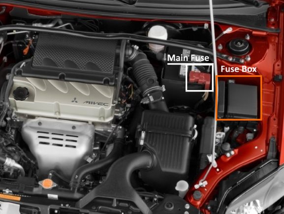
Location of components.
Main fuse
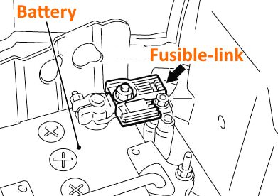
It is in the form of a power fusible link and is located on the plus terminal of the battery.
Fuse box
Located on the left side, next to the battery.
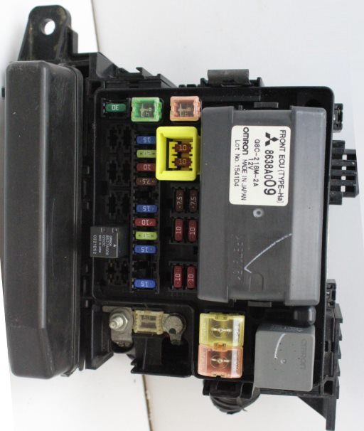
General view.
| Diagram | ||
|---|---|---|

|
||
| № | Amps / Description | Amps |
| 1 | Battery | 80 |
| 2 | Cooling fan motor | 30 / 50 |
| 3 | ABS system | 60 |
| 4 | Ignition Lock Circuit | 40 |
| 5 | Power windows | 30 |
| 6 | Fog lights | 15 |
| 7 | Heated seats | 15 / 20 |
| 8 | Buzzer | 20 |
| 9 | Engine management system | 20 |
| 10 | A / C Compressor Electromagnetic Clutch | 10 |
| 11 | Stop lamps | 15 |
| 12 | Rear fog lamps | 10 |
| 13 | Alternator | 7.5 |
| 14 | Alarm | 10 |
| 15 | Electronic transmission control unit | 20 |
| 16 | Right main beam headlight | 10 |
| 17 | Left main beam headlight | 10 |
| 18 | Right dipped beam headlight | 10 |
| 19 | Left dipped beam headlight | 10 |
| 20 | ,Parking Lights, right | 7.5 |
| 21 | Parking Lights, left | 7.5 |
| 22 | Interior lamps | 10 |
| 23 | Audio system | 10 |
| 24 | fuel pump | 15 |
| 25 | Windshield cleaner | 30 |
| R1 | Fog lamp relay | |
| R2 | Windshield heater relay | |
| R3 | Accessory Power Connector Relay | |
| R4 | Horn relay | |
| R5 | Fog lamp relay | |
| R6 | Cooling fan motor relay | |
| R7 | A / C compressor electromagnetic clutch relay | |
| R8 | Engine control relay | |
| R9 | Electronic transmission control unit relay | |
| R10 | Ignition relay | |
| R11 | Throttle control unit relay | |
| R12 | Spare | |
| R13 | Spare | |
In the passenger compartment
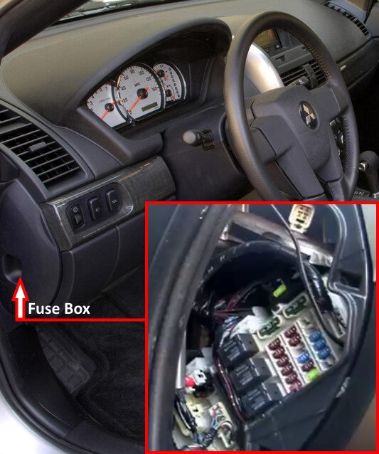
Located at the end of the instrument panel behind the protective cover.
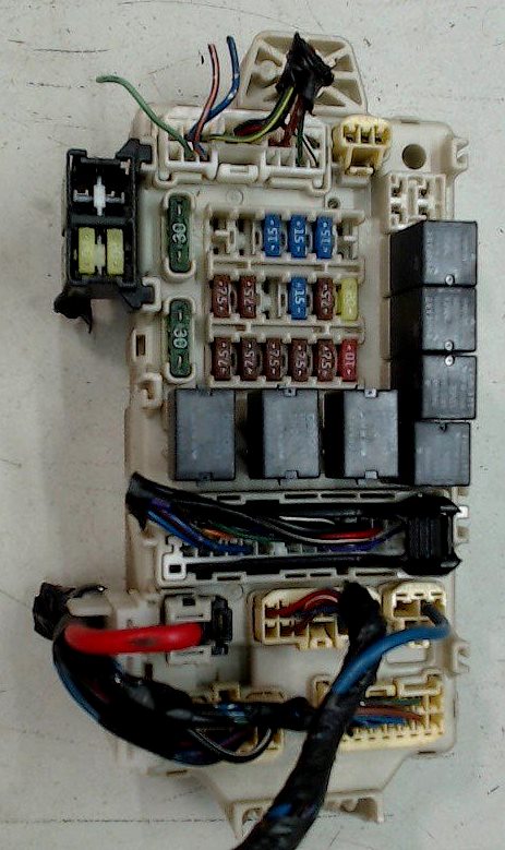
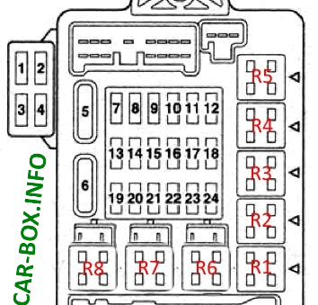
General view of the Mitsubishi Galant 9 interior fuse box.
| Diagram | ||
|---|---|---|
|
||
| № | Description | Amps |
| R1 | Fuel pump relay (1) | |
| R2 | Relay for auxiliary equipment connection socket | |
| R3 | Fuel pump relay (2) | |
| R4 | Front seat heating relay | |
| R5 | Rear fog lamp relay | |
| R6 | Power window relay | |
| R7 | Heater fan motor relay | |
| R8 | Rear window heater relay | |
| 1 | Spare | - |
| 2 | Spare | - |
| 3 | Audio amplifier | 30 |
| 4 | Sunroof | 20 |
| 5 | Heated rear window, interference suppression capacitor | 30 |
| 6 | Heater fan motor | 30 |
| 7 | Spare | - |
| 8 | Spare | - |
| 9 | Connector for connection of additional electrical equipment | 15 |
| 10 | Diagnostic socket, Central locking, ETACS control unit | 15 |
| 11 | ETACS control unit | |
| 12 | Spare | - |
| 13 | Electrochromic rear view mirror | 7.5 |
| 14 | Electric side rear view mirrors | 7.5 |
| 15 | Spare | - |
| 16 | Mitsubishi Galant 9 cigarette lighter fuse | 15 |
| 17 | Fuel pump relay; engine and automatic transmission control unit | 7.5 |
| 18 | Spare | - |
| 19 | Heated side mirrors | 7.5 |
| 20 | Relay | 7.5 |
| 21 | Spare | - |
| 22 | Rear combination lamps, automatic transmission controls | 7.5 |
| 23 | Multifunction display, Steering column switch, Control units (ABS, ETACS, SRS) | 7.5 |
| 24 | Ignition coil | 10 |
