Grandis is a minivan produced in 6- and 7-seat variants by Japanese company Mitsubishi Motors. It is equipped with ABS anti-lock brakes, EBD electronic brake force distribution system and emergency brake booster. In this article, we will take a detailed look at the fuse box diagrams for the Mitsubishi Grandis (1st generation; codename NA4W, NA8W) 2003, 2004, 2005, 2005, 2006, 2007, 2008, 2009, 2010, 2011 years of manufacture.

Here you will find the locations and photos of distribution boxes. The fuses responsible for the “Cigarette lighter” and “Fuel Pump” are highlighted in bold.
In the engine compartment

Located on the left side. It consists of a main unit and an auxiliary panel. The design of the additional panel may differ depending on the type of engine installed (diesel or gasoline).
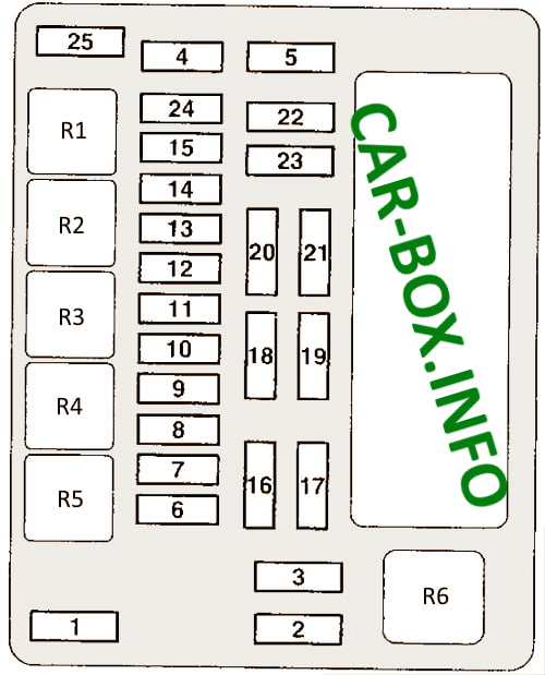
Main distribution unit
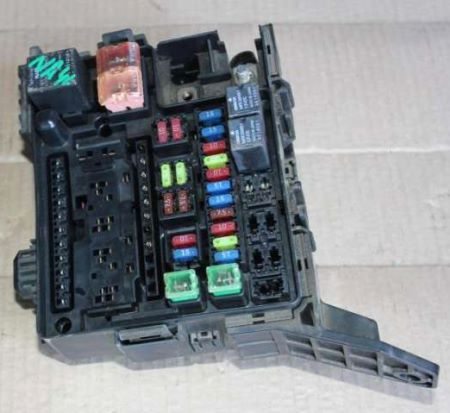
General view.
| Diagram | ||
|---|---|---|
|
||
| № | Description | Amps |
| R1 | Accessory Power Connector Relay | |
| R2 | Horn or alarm relay | |
| R3 | Purifier relay | |
| R4 | Horn or alarm relay | |
| R5 | Fog lamp relay | |
| R6 | Cooling fan relay | |
| 1 | Dashboard fuse / relay box Battery / Spare | 60 / 80 / - |
| 2 | Cooling fan motor | 50 |
| 3 | ABS system | 30 |
| 4 | Ignition Lock Circuit | 40 |
| 5 | Power windows | 40 |
| 6 | Fog lights | 15 |
| 7 | AC power supply providing additional outlets | 15 / 20 |
| 8 | Buzzer | 10 |
| 9 | Engine control module | 20 |
| 10 | A/C compressor solenoid clutch | 10 |
| 11 | Stop lights | 15 |
| 12 | Heated windshield, horn | 15 |
| 13 | Alternator | 7.5 |
| 14 | Alarm | 10 |
| 15 | Electronic transmission control unit | 20 |
| 16 | High beam, right headlight | 10 |
| 17 | High beam left headlight | 10 |
| 18 | Right dipped beam headlight | 10 |
| 19 | Left dipped beam headlight | 10 |
| 20 | Rear light (right) | 7.5 |
| 21 | Rear light (left) | 7.5 |
| 22 | Reserve / engine management | 15 |
| 23 | Audio system | 10 |
| 24 | fuel pump fuse | 15 |
| 25 | Electric tailgate | 30 |
Auxilary panel
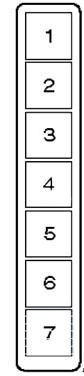
Cars with diesel engine
Diagram
Designation
- Condenser fan 30A;
- Engine control unit30A;
- Regulating flap 10A;
- Ignition relay 10A;
- Valve block 10A;
- Electronic anti-theft device 7.5A;
- Heating module 10A
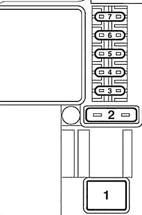
Cars with gasoline engine
Diagram
Description
1 - A/C compressor solenoid clutch relay;
2 - Engine control relay;
3 - Relay of the electronic transmission control unit;
4 - Ignition relay;
5 - Throttle control unit relay;
6 - Spare;
7 - Spare.
In the passenger compartment
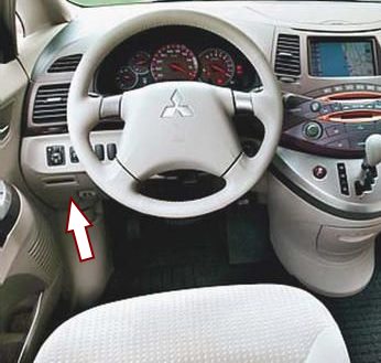
It is located under the dashboard on the left side, behind the dashboard trim.

General view of the Mitsubishi Grandis interior fuse box.
| Diagram | ||
|---|---|---|

|
||
| № | Description | Amps |
| R1 | Fuel pump relay (1) | |
| R2 | Front seat heating relay | |
| R3 | Fuel pump relay (2) | |
| R4 | relay for the auxiliary equipment connection socket; | |
| R5 | Rear fog lamp relay | |
| R6 | Power window relay | |
| R7 | Heater fan motor relay | |
| R8 | Rear window heater relay | |
| 1 | Ignition system | 10 |
| 2 | Instrument cluster (panel) | 7.5 |
| 3 | Reverse lights, automatic transmission control relay | 7.5 |
| 4 | Cruise control system | 7.5 |
| 5 | Relay | 7.5 |
| 6 | External mirror control panel | 7.5 |
| 7 | Cleaners and washers, Electronic lighting control unit | 30 |
| 8 | Electronic engine and automatic transmission control unit (for vehicles with automatic transmission), electronic engine control unit, fuel pump relay | 7.5 |
| 9 | Mitsubishi Grandis сigarette lighter fuse | 15 |
| 10 | Spare | - |
| 11 | Power mirrors | 7.5 |
| 12 | Engine control module | 7.5 |
| 13 | Audio system, Radio | 10 |
| 14 | Rear window wiper / washer | 15 |
| 15 | Central locking | 15 |
| 16 | Rear fog lamp | 10 |
| 17 | Spare | - |
| 18 | Interior lamps | 10 |
| 19 | Heater blower motor | 30 |
| 20 | Heated rear window | 30 |
| 21 | Sunroof motor | 20 |
| 22 | Heated seats | 20 |
| 23 | Rear air conditioner | 20 |
| 24 | Starter | 10 |
