
The Peugeot 408 debuted in early 2010 at the Beijing Motor Show. Despite its model designation, it is not the successor to the 407, but rather a sedan derivative of the 308 hatchback. Designed as a global model, it was developed primarily for the Russian, Chinese, and Latin American markets. This article provides comprehensive fuse box diagrams and terminal assignments for the first-generation Peugeot 408 (chassis code T7; PSA PF2 platform; model years 2012–2017).

Below are the locations, diagrams, and photographic guides for all power distribution blocks. Fuses for key circuits, such as the “Cigarette Lighter” and “Fuel Pump,” are bolded for quick identification.
Passenger Compartment Fuse Box
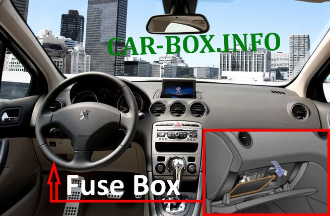
The fuse box is located under the instrument panel on the driver’s side.
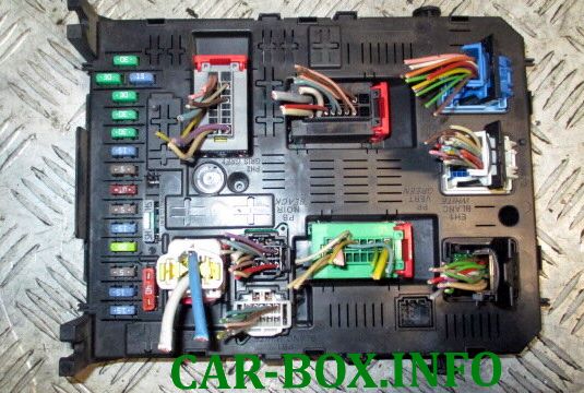
General overview of the Peugeot 408 passenger compartment fuse box.
| Diagram | ||
|---|---|---|

|
||
| Fuse No. | Circuit Description | Rating (A) |
| F2 | Central locking system | 30 |
| F3 | Airbag control module, seat belt pretensioners, power exterior mirrors | 5 |
| F4 | Clutch pedal switch, dual-function brake light switch, air conditioning system, steering angle sensor, automatic transmission ECU, ESC module | 10 |
| F5 | Front power windows | 30 |
| F6 | Rear power windows | 30 |
| F7 | Front and rear courtesy lamps, map reading lamps, vanity mirror illumination, glove box lamp | 5 |
| F8 | Audio system, multi-function display, alarm system pre-equipment | 20 |
| F9 | Front 12 V power socket, audio system pre-equipment, cigarette lighter | 30 |
| F10 | Automatic transmission control unit, brake light switch | 15 |
| F11 | Ignition switch circuit | 15 |
| F13 | Engine Control Module (ECM / ECU) | 5 |
| F14 | Instrument cluster, airbag control unit, automatic climate control, multi-function display | 15 |
| F15 | Central locking system | 30 |
| F17 | Heated rear window and heated exterior mirrors | 40 |
Engine Compartment Fuse Box
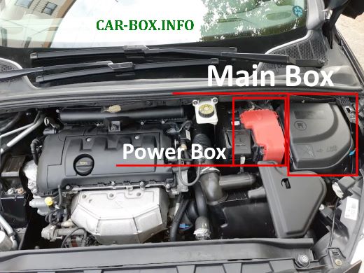
The engine compartment houses two distribution blocks: the main fuse box adjacent to the battery, and a high-current power fuse panel mounted directly on the positive battery terminal.
Main Fuse Box
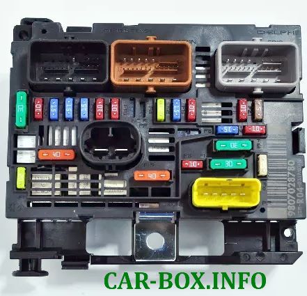
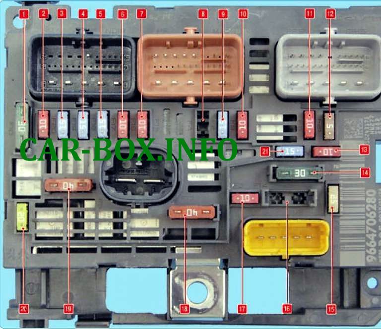
Representative photograph of the main fuse box assembly.
| Diagram | ||
|---|---|---|
|
||
| Fuse No. | Circuit Description | Rating (A) |
| 1 | Engine management components (petrol): ignition coils, solenoid valves, oxygen (lambda) sensors, fuel injectors, canister heating components, fuel pump, controlled thermostat | 30 |
| 2 | Spare | 10 |
| 3 | Ignition coils | 15 |
| 4 | Right headlight (low beam) | 15 |
| 5 | Left headlight (low beam) | 15 |
| 6 | Left headlight (high beam) | 10 |
| 7 | Right headlight (high beam) | 10 |
| 8 | Headlight washer pump | 20 |
| 9 | Horn | 15 |
| 10 | Engine coolant level sensor, headlight leveling actuators | 10 |
| 11 | Vehicle speed sensor, ABS/ESP control module, automatic transmission ECU | 10 |
| 12 | Radiator cooling fan relay power supply | 5 |
| 13 | Electric power steering (EPS) control module | 10 |
| 14 | Windshield wiper motor (low/high speed) | 30 |
| 15 | Starter motor solenoid switch | 25 |
| 16 | Spare | - |
| 17 | Windshield washer pump | 10 |
| 18 | Built-in Systems Interface (BSI) power supply (+12 V switched ignition) | 40 |
| 19 | Climate control blower fan | 40 |
| 20 | Engine Control Unit (ECU) main power supply | 20 |
| 21 | EVAP canister purge solenoid valve, fuel pump | 15 |
Battery Power Fuse Panel
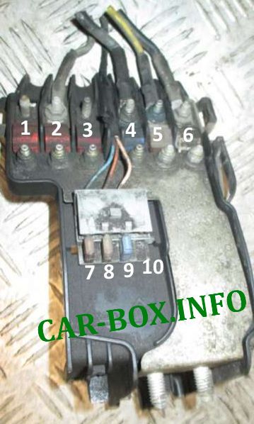
Mounted directly on the positive terminal of the battery.
| Diagram | ||
|---|---|---|
| Type 1 | ||
|
||
| Fuse No. | Circuit Description | Rating (A) |
| 1 | Valvetronic variable valve lift motor (1.6L THP 16V) | 30 |
| 2 | Automated manual / sequential gearbox hydraulic pump | 30 |
| 3 | Spare | 50 |
| 4 | Protection and Switching Module (BPGA / BSM supply) | 100 |
| 5 | Glow plug control module (diesel engine) | 70 |
| 6 | Electro-hydraulic power steering (EHPS) pump | 80 |
| 7 | Transmission control unit (automatic or sequential) | 15 |
| 8 | Diagnostic link connector (OBD-II port), daytime running lights (DRL) | 15 |
| 9 | Dual-function brake light switch | 5 |
| 10 | Spare | - |
| Type 2 | ||
|
||
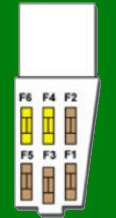
| F1 | Automatic transmission control unit | 15 |
| F2 | Diagnostic link connector (OBD-II port) | 15 |
| F3 | Brake lights / stop light switch | 5 |
| F4 | Heated windshield washer nozzles | 5 |