
The second-generation Peugeot Partner, officially introduced in January 2008, made its public debut at the Geneva Motor Show in March 2008. This article provides a comprehensive guide to the fuse box diagrams for the Peugeot Partner (2nd generation; chassis code B9; PSA PF2 platform, including the Tepee variant) produced from 2008 through 2020.
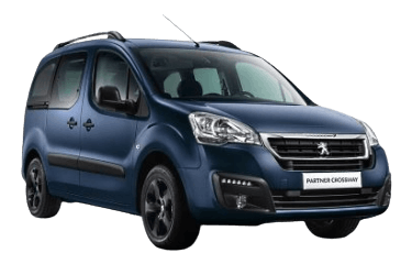
Below you will find fuse box locations, layout diagrams, and component photos. Fuses dedicated to the "Cigarette Lighter" and "Fuel Pump" are highlighted in bold text.
Passenger Compartment Fuse Box

Located on the left side under the dashboard.
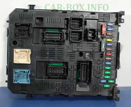
General view.
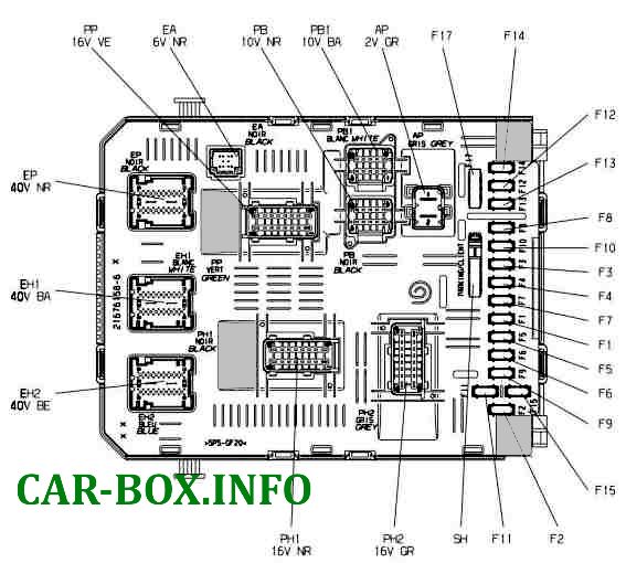
| Diagram | ||
|---|---|---|
|
||
| No. | Description | A |
| F1 | Rear window wiper motor | 15 |
| F2 | Not used | |
| F3 | Airbag control unit (SRS) | 5 |
| F4 | Air conditioning, diagnostic socket (OBD2), electrochromic rear view mirror, headlight leveling switch | 10 |
| F5 | Power windows | 30 |
| F6 | Central locking system | 30 |
| F7 | Rear dome light, front reading lights, sunroof switch | 5 |
| F8 | Audio unit, CD changer, multi-function display, Tyre Pressure Monitoring System (TPMS), alarm ECU and siren | 20 |
| F9 |
|
30 |
| F10 | Steering column switch unit (COM2000) | 15 |
| F11 | Ignition switch low-current circuit | 15 |
| F12 | Rain and light sensor, airbag control unit (SRS) | 15 |
| F13 | Instrument panel cluster | 5 |
| F14 | Parking assistance (Parktronic), A/C control module, hands-free kit | 15 |
| F15 | Central locking power supply | 30 |
| F16 | Not used | |
| F17 | Heated rear window and heated exterior mirrors | 40 |
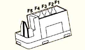
| Auxiliary fuse panel (adjacent to the main unit) | ||
|
||
| F1 | Not used | - |
| F2 | Heated seats module | 20 |
| F3 | Not used | - |
| F4 | Power folding door mirrors relay | 15 |
| F5 | Fridge power socket relay | 15 |
An additional fuse box is provided for towbar/trailer wiring hookups. Located on the right-hand side behind the partition wall, it is installed only on vehicles fitted with trailer towing equipment.

|
||
| No. | Description | A |
| F1 | Ignition switch relay, auxiliary alternator relay | 15 |
| F2 | 12 V power supply for trailer socket | 15 |
| F3 | Direct current (DC) supply circuit for body conversions | 15 |
| F4 | Hazard warning lights | 40 |
Engine Compartment Fuse Box
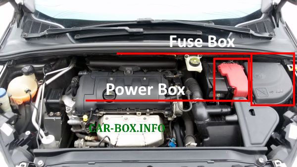
Location of the underhood distribution boxes.
Underhood Fuse Unit
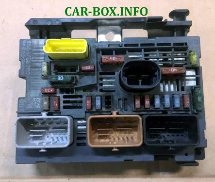
General view of the engine compartment fuse box.
| Diagram | ||
|---|---|---|
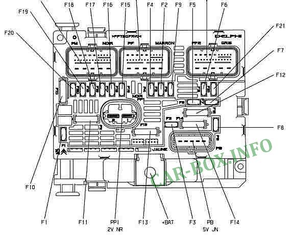
|
||
| No. | Description | A |
| F1 | Engine Control Unit (ECU) supply, dual-speed radiator cooling fan control unit | 20 |
| F2 | Horn assembly | 15 |
| F3 | Windscreen and rear window washer pump | 10 |
| F4 | Headlight washer pump | 20 |
| F5 |
|
15 |
| F6 |
|
10 |
| F7 |
|
10 |
| F8 | Starter motor solenoid coil | 25 |
| F9 | Ignition switched live supply to 3-relay protection/interlocking module, headlamp levelling actuator motors | 10 |
| F10 | Ignition coil supply (TU5JP4), fuel injector supply (TU5JP4), high-pressure fuel pump solenoid valve (DV6) | 30 |
| F11 | Blower motor fan relay energization circuit | 40 |
| F12 | Front windscreen wiper low and high speed controls | 30 |
| F13 | Ignition switched live supply to Built-in Systems Interface / Body Control Module (BSI / BCM) | 40 |
| F14 | Exhaust gas temperature recovery system pump control | 30 |
| F15 | Right-hand high beam headlight | 10 |
| F16 | Left-hand high beam headlight | 10 |
| F17 | Left-hand low beam (dipped) headlight | 15 |
| F18 | Right-hand low beam (dipped) headlight | 15 |
| F19 |
|
15 |
| F20 |
|
10 |
| F21 |
|
5 |
Battery Main Power Fuse Module
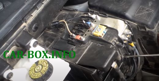
Location and access to the battery-mounted power fuse module.
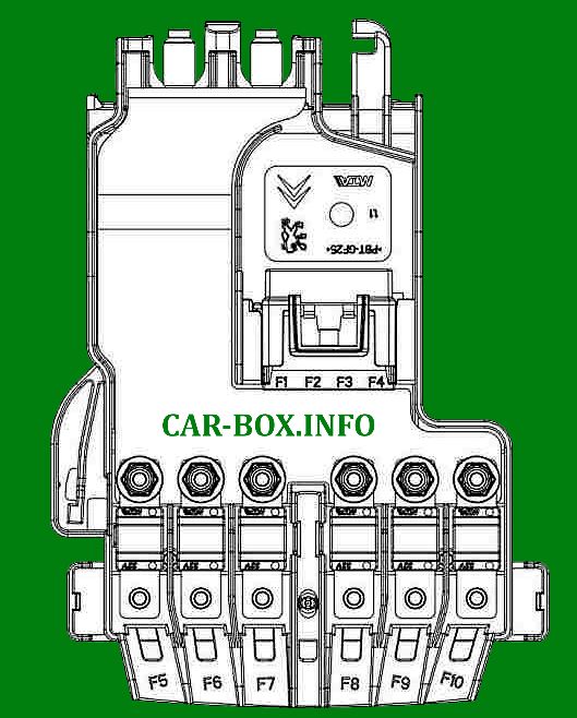
|
||
| No. | Description | A |
| F1 | Battery charge monitoring module (BPMU) | 5 |
| F2 | Diagnostic connector socket (OBD2) | 15 |
| F3 | Brake pedal switch resistors circuit | 15 |
| F4 | Not used | |
| F5 | Electric power steering (EPS) pump unit power supply | 80 |
| F6 | Glow plug pre-heating / post-heating control unit | 70 |
| F7 | 3-relay protection/interlocking module | 100 |
| F8 | Not used | |
| F9 | Not used | |
| F10 | Engine protection relay supply | 30 |

Fuse for the horn?
WHERE IS THE FUSE FOR THE HORN?
where is the fuse supplying lights in the cargo bay of my van 2018 year mark 2 Peugeot partner