Koleos is a compact crossover. It is manufactured by Renault at its plant in Busan, South Korea. This is the first specially designed SUV, which was released by the French automaker. In this material, we will understand in detail the fuse box diagrams of Renault Koleos (second generation; internal designation HC; CMF-CD platform) 2016, 2017, 2018, 2019, 2019, 2020, 2021, 2022, 2023, 2024 year of manufacture.

Here you will find the locations and photos of distribution boxes. Separately note the fuses responsible for the cigarette lighter and fuel pump.
In the engine compartment
Here are five blocks responsible for protection of car electrical circuits.
Power fuses

They are located on the plus terminal of the battery.
| Diagram | ||
|---|---|---|

|
||
| № | Description | Amps |
| F1 | Starter | 450A |
| F2 | Generator | 450A |
| F3 | Protection of fuses F1, F2, F3, F4, F5, F6, F7, F8, F9, F10, F11, F12, F13, F14, F15 and F16 on the board (777); protection of fuses F1 and F2 on the board (1793) in ‘MICROHIBRID’ modification | 100A |
| F4 | Protection and communication unit (1337); F4 fuse protection on board (1792) | 100A |
| F5 | Additional cabin heater | 50A |
| F6 | Relay after ignition switch, Window heater, Protection of fuses F1, F2, F3, F4, F5, F6, F7, F8, F9, F10, F11, F12, F13, F14, F15, F16 and F22 on board (260) | 100A |
| F7 | Protection and communication unit (1337) | 100A |
Fuse boxes #1 and #2

They are located under the air intake pipe.

The air intake spigot must be removed for access.
Fuse box No. 1

General view.

Description from the rear cover of the unit.
| Diagram | ||
|---|---|---|

|
||
| № | Description | Amps |
| F | ESP system | 50A |
| G | ABS system | 30A |
| H | ESP system | 50A |
| I | Headlight washer relay | 30A |
| J | Empty | |
| K | ABS system | 40A |
| L | Starter relay, ignition relay (fuse protection: “1”, “2”, “3”, “4”, “10”, “11”, “12”) | 30A |
| M | Power window relay, power windows, power curtain, power seats | 50A |
| R1 | Horn relay | |
| 34 | Horn relay | 15A |
| 35 | Diesel engine: PTC 2 relay | 30A |
| 36 | Diesel engine: PTC 3 relay | 30A |
| 37 | Diesel engine: Relay PTC 1 | 30A |
| 38 | Electric parking brake | 30A |
| 39 | Optional connector | 30A |
| 40 | Empty | |
| 41 | Electric parking brake | 30A |
Fuse box No. 2

General view.
| Diagram | ||
|---|---|---|

|
||
| № | Description | Amps |
| 81 | Engine Control Unit (Injection ECU) | 10A |
| 82 | Engine control unit (Injectors) | 15A |
| 83 | Throttle valve, engine control unit, EVAP, air mass flow sensor, ignition coils, main relay, exhaust valve, intake valve, high pressure fuel pump, injectors, engine compartment fuse box, fuel air ratio sensor, fuel heater, fuel water sensor, coolant bypass valve | 15A |
| 84 | Engine control unit, intake manifold valve, exhaust manifold valve, timing valve, intake timing valve, intermediate timing valve. | 10A |
| 85 | Air-fuel ratio sensor, heated oxygen sensor, turbocharger valve, engine control unit, glow plug control unit. | 15A |
| 86 | Injectors, ignition coils, fuse box | 15A |
| 87 | Air conditioner compressor relay | 15A |
| 88 | ABS system | 10A |
| 89 | Coolant pump | 15A |
| 90 | Front wiper relay, front wiper motor | 30A |
| 91 | Fuel pump relay (gasoline pump fuse) | 20A |
| 92 | Starter | 30A |
| 93 | Engine control unit, transmission control unit, transmission range sensor, engine compartment fuse box, neutral position sensor, primary speed sensor, secondary speed sensor, revolutions sensor, reverse/neutral sensor | 10A |
| 94 | EPS system | 5A |
| 95 | Steering wheel lock unit | 5A |
| 96 | Restart relay (start/stop) / ABS system | 10A |
| 97 | Front right combination lamp, front left combination lamp, compressor, transmission range sensor, engine compartment fuse box, neutral position sensor, reverse gear switch, reverse/neutral sensor | 10A |
Additional fuse boxes
Their presence under the hood depends on the vehicle configuration.
Unit No. 1
Located under the headlight.
Diagram

No. | Purpose
HEATED SCREEN. | Glass heating.
H/LAMP WASHER RELAY. | Headlamp washer relay.
ANTI THEFT HORN RELAY. | Anti-theft alarm horn relay.
HEATED FRONT SCREEN RELAY. | Windshield heater relay.
Unit No. 2

General view.

No. | Purpose
RAD_FAN. | radiator fan.
STARTER RELAY. | starter relay.
USM. | fuse and relay box under the hood.
CVT OIL PUMP RELAY. | Transmission oil pump relay.
CVT CONT. | automatic transmission control unit.
FUEL HEATER. | Fuel heater.
In the passenger compartment
Here there are two fuse boxes responsible for the protection of the vehicle's electrical circuits.
Fuse box No. 1

It is located at the end of the dashboard on the driver's side.
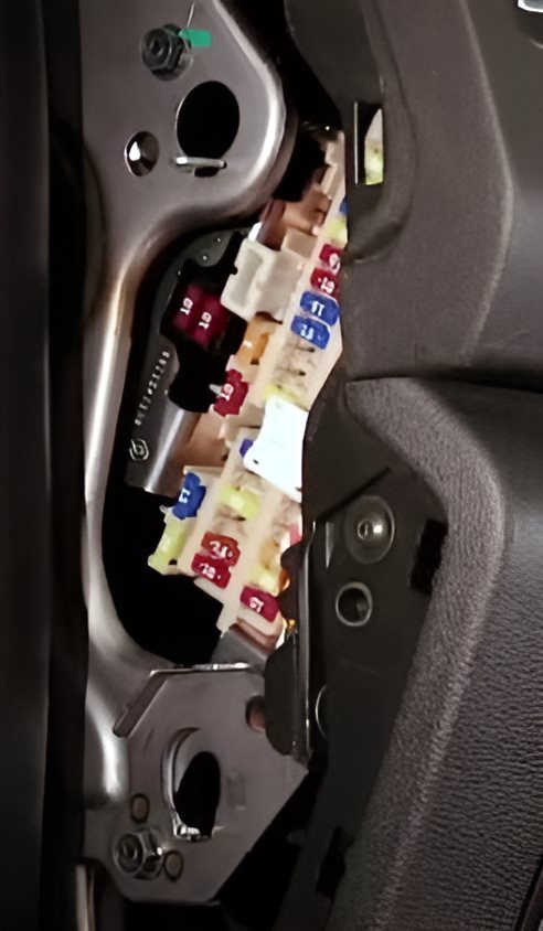
Example of access.
| Diagram | ||
|---|---|---|

|
||
| № | Purpose | Amps |
| 1 | Double-acting windshield and rear window washer pump (677) via paddle switch assembly (1519), Instrument panel | 10A |
| 2 | Steering wheel heating fuse: protection of fuse f3 on the circuit board | 10A |
| 3 | Empty | - |
| 4 | Auxiliary equipment socket | 10A |
| 5 | Empty | - |
| 6 | Seat heating | 15A |
| 7 | Heater, A/C booster, Engine Restart Baypass Control relay | 20A |
| 8 | Empty | - |
| 9 | Empty | - |
| 10 | Rear window heater | 15A |
| 11 | Rear window heating | 15A |
| 12 | Mirror heating | 10A |
| 13 | ABS system or brake lights | 10A |
| 14 | 20A | |
| 15 | Renault Koleos 2 cigarette lighter fuse | 15A |
| 16 | Interior lighting | 20A |
| 17 | Heater motor, resistor, air conditioner booster | 20A |
| 18 | Audio system | 10A |
| 19 | Audio system, navigation control unit, surround view camera | 20A |
| 20 | Body electronics module (BCM), siren, multifunction switch | 5A |
| 21 | Empty | - |
| 22 | Empty | - |
| 23 | Audio | 20A |
| 24 | Stop lamp switch, body electronics module (BCM) | 10A |
| 25 | Four-wheel drive, anti-theft system antenna amplifier | 5A |
| 26 | Empty | - |
| 27 | Body electronics module (BCM), multifunction switch | 10A |
| 28 | Body electronics module (BCM), electric parking brake, diagnostic connector, four-wheel drive, instrument panel illumination/switches, power window relay, mirror folding relay, mirror opening relay | 10A |
| 29 | Central locking, body electronics module (BCM) | 20A |
| 30 | Glass washer | 15A |
| 31 | Central locking, body electronics module (BCM) | 20A |
| 32 | Empty | - |
| 33 | Emergency alarm and direction indicators | 15A |
| 34 | Interior lighting | 10A |
| 35 | Heating | 10A |

Relay modules at the back of the unit:
R1. | Ignition system
R2. | Front engine fan
R3. | Rear window heater
R4. | Auxiliary relay after ignition switch
Fuse box No. 2

Located at the end of the instrument panel on the passenger side.
| Diagram | ||
|---|---|---|

|
||
| № | Description | Amps |
| R1 | Auxiliary relay | - |
| R2 | Ignition | - |
| 71 | Steering angle sensor | 10A |
| 72 | Instrument cluster | 10A |
| 73 | Audio system, navigation control unit, surround view camera | 10A |
| 74 | Transmission Control Module (TCM) | 10A |
| 75 | Empty | - |
| 76 | Air conditioner control unit, air conditioner booster | 10A |
| 77 | ABS system | 10A |
| 78 | Blank | - |
| 79 | Oil pump relay | 10A |
| 80 | Audio system, navigation control unit, surround view camera | 20A |
| 81 | Transmission Control Module (TCM) | 10A |
