Renault Scenic and Grand III (extended 7-seater modification) were produced in 2009, 2010, 2011, 2012, 2013, 2014, 2015 and 2016. During this time, this series has been restyled 2 times.
We will show you where the fuse and relay blocks are located in the 3rd generation, their diagrams and the purpose of the elements.
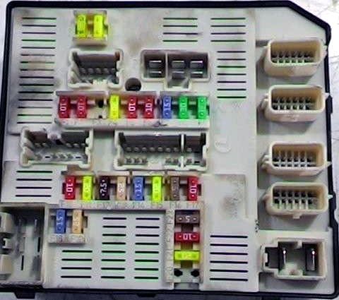
In the passenger compartment
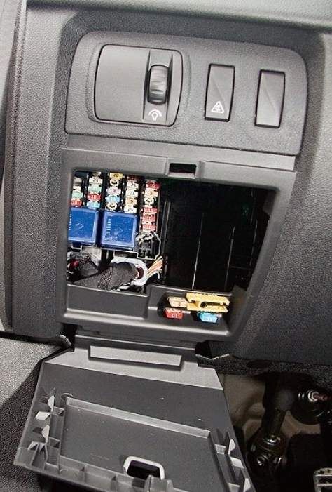
The fuse box is located on the driver's side. To access it, you need to remove the protective cover.
| Assignment of the fuses in the passenger compartment | ||
|---|---|---|
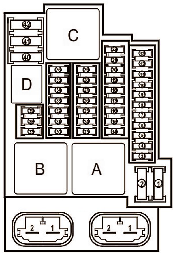
|
||
| No. | Description | A |
| A | power relay (+ battery) with delayed shutdown (without power off at startup) | 70 |
| B | power relay (+ battery) with delayed shutdown (with power off at startup) | 70 |
| C | rear window heating relay | 40 |
| D | horn relay | 20 |
| 1 | right windscreen wiper fuse | 40 |
| 2 | left windshield wiper fuse | 40 |
| 3 | cigarette lighter scenic 3 | 10 |
| 4 | rear power outlet | 10 |
| 5 | luggage compartment power outlet | 10 |
| 6 | audio system | 10 |
| 7 | heated exterior mirrors | 5 |
| 8 | windshield washer, open door signaling device | 10 |
| 9 | automatic parking brake | 30 |
| 10 | Spare | |
| 11 | power seat, steering column switches | 25 |
| 12 | running engine relay | 20 |
| 13 | Spare | |
| 14 | front passenger door window regulator | 25 |
| 15 | brake light switch, brake pedal position sensor, ABS / ESP control unit | 5 |
| 16 | window regulator of the right rear door | 25 |
| 17 | window regulator of the left rear door | 25 |
| 18 | glove compartment lighting, left luggage compartment lighting, door lighting, mirror lamps in sun visors, rain sensor | 10 |
| 19 | clock, outside temperature indicator, seat belt warning indicator, audio system connector | 10 |
| 20 | air conditioning control unit | 5 |
| 21 | mirror lamps in sun visors | 3 |
| 22 | interior lampshades, rain and light sensor | 3 |
| 23 | trailer connector | 25 |
| 24 | UCH | 15 |
| 25 | Spare | |
| 26 | navigation system, CD changer, audio system | 10 |
| 27 | audio system, parking brake control unit | 20 |
| 28 | Spare | |
| 29 | Spare | |
| 30 | UCH, direction indicators | 15 |
| 31 | UCH | 10 |
| 32 | driver's door window regulator | 30 |
| 33 | UCH, central locking | 25 |
| 34 | Passenger door multiplex network ECU | 30 |
| 35 | clock, outside temperature gauge, phone display | 15 |
| 36 | diagnostic socket, horn relay, alarm control unit, siren | 15 |
| 37 | brake signals, electrical control unit | 10 |
| 38 | automatic parking brake | 30 |
| 39 | Spare | |
| 40 | air conditioner fan, instrument panel | 40 |
| 41 | electric sunroof | 25 |
| 42 | heated rear window | 40 |
A separate 40A "+" relay module with the engine running can be under the passenger seat. And there can be 3 additional heating relays on the center console heater block.
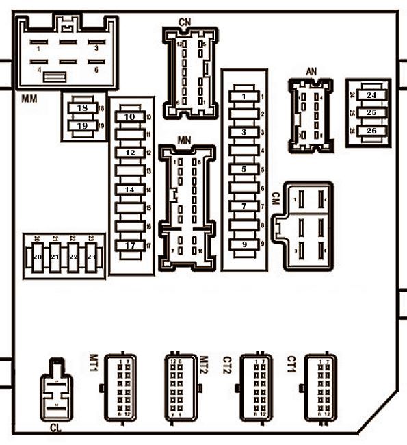
In the engine compartment
The main fuse box is located on the right side of the engine compartment.
Main block
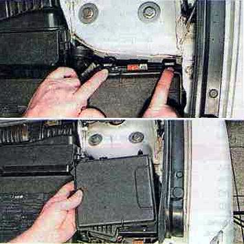
Access example.
General view.
| Assignment of the fuses in the engine protection and switching box | ||
|---|---|---|
|
||
| No. | Decoding | A |
| 1 | Side light (right headlight, right tail light, headlights), license plate lights, cigarette lighter lights, power window switch lights, audio system, navigation system control unit, multimedia system keyboards | 10 |
| 2 | Side light (left headlamp, left tail light), left tailgate light | 10 |
| 3 | Headlight washer pump | 15 |
| 4 | Fog lights | 20 |
| 5 | High beam (left headlight unit) | 10 |
| 6 | High beam (right headlamp) | 10 |
| 7 | Diagnostic socket, rear window defogger relay, automatic transmission mode selector, electro-corrector of headlights, gas discharge lamp control unit, auxiliary heater control unit, speed limiter, automatic parking brake, automatic parking control unit, interior mirror | 15 |
| 8 | ABS / ESP ECU | 30 |
| 9 | Front wiper | 30 |
| 10 | Airbag control unit | 10 |
| 11 | Spare | 20 |
| 12 | Transmission ECU | 7.5 |
| 13 | Engine management system | 25 |
| 14 | Oxygen sensors - heating | 15 |
| 15 | Transmission ECU | 20 |
| 16 | Brake signals, electrical control unit, electric power steering | 5 |
| 17 | Automatic transmission operating mode sensor, headlight corrector, reverse light relay | 10 |
| 18 | UCH | 15 |
| 19 | Starter | 25 |
| 20 | Spare | |
| 21 | Fuel pump, ignition coils, LPG ECU | 20 |
| 22 | A / C Compressor Electromagnetic Clutch | 10 |
| 23 | Injection computer | 5 |
| 24 | Low beam (left headlight), electrocorrector | 20 |
| 25 | Dipped beam (right headlight), electrocorrector | 20 |
| 26 | Spare | |
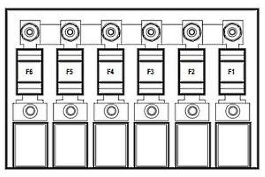
Additional fuse box

Located under the protection block (mainly diesel engines)
| Additional block diagram | ||
|---|---|---|

|
||
| No. | Decoding | A |
| F1 | immersion heater control | 80 |
| F2 | preheating unit | 70 |
| F3 | Empty | |
| F4 | immersion heater control | 80 |
| F5 | fan relay | 60/40 |
| F6 | Fuel heater relay | 20 |
| F7 | Empty | |
| F8 | fan relay | 30 |
| F9 | Empty | |
| A | Empty | |
| B | Fuel heater relay | |
| C | Reverse light relay | |
| D | Empty | |
Near the battery
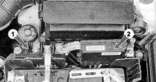
There are two blocks near the battery: a battery shutdown unit (1) and high-power fuse-links (2).
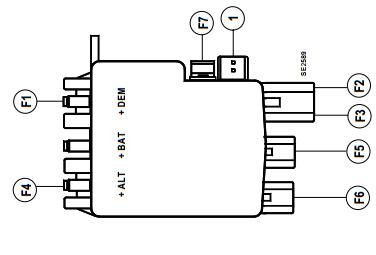
| Battery block diagrams | ||
|---|---|---|
| No. | Description | A |
| Battery shutdown unit (1) | ||
|
||
| F1 | Starter | 190 |
| F2 | passenger compartment fuse box | 50 |
| F3 | control and switching unit in the engine compartment 1, fuse and relay box in the passenger compartment | 80 |
| F4 | engine compartment unit 2 / generator | 300/190 |
| F5 | electric power steering | 80 |
| F6 | electronic engine control unit (ECU) / fuse and relay box (control and switching unit) in the engine compartment 1 | 35 |
| F7 | control and switching unit in the engine compartment 1 | 5 |
| Fuse links (2) | ||
|
||
| F1 | additional interior heater | 70 |
| F2 | passenger compartment fuse box | 80 |
| F3 | 80 | |
| F4 | control and switching unit in the engine compartment 1, fuse and relay box in the passenger compartment | 80 |
| F5 | additional heater | 30 |
| F6 | ABS / trajectory stabilization systems | 50 |
