Subaru Forester SJ was introduced in November 2012. In Japan, it was offered with two-liter opposition four-cylinder engines rated at 146 hp (198 N-m) and 276 hp (350 N-m). In the U.S. was additionally equipped with a 2.5-liter engine with an output of 173 hp, in Europe with a two-liter diesel engine with an output of 150 hp. In this article, we will take a detailed look at the fuse box diagrams for the Subaru Forester (4Gen; body indices SJ5, SJ9, SJG) 2012, 2013, 2014, 2015, 2016, 2017, 2018, 2019 years of manufacture.
Here you will find the locations and photos of distribution boxes. The fuses responsible for the “Cigarette lighter” and “Fuel Pump” are highlighted in bold.
In the engine compartment
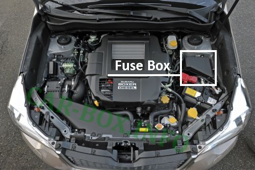
The fuse box is located on the left side of the engine compartment.
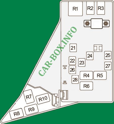
General view.
| Diagram | ||
|---|---|---|

|
||
| No. | Description | A |
| A | ABS Unit, Vehicle Dynamics Control Unit | 120 |
| 1 |
|
30 |
| 2 | Main fan (radiator fan) | 25 |
| 3 | Auxiliary fan (radiator fan) | 25 |
| 4 | Not installed | - |
| 5 | Audio system | 25 |
| 6 | Headlight bulb | 30 |
| 7 | Headlight bulb | 15 |
| 8 | Backup power supply circuit | 20 |
| 9 | Horn (beep) | 15 |
| 10 |
|
25 |
| 11 | Subaru Forester fuel pump fuse | 20 |
| 12 | Vario transmission control unit | 20 |
| 13 | The engine control unit | 7.5 |
| 14 | Turn indicators and emergency warning lights | 15 |
| 15 | Position lamp and lighting relay | 15 |
| 16 | Alternator | 7.5 |
| 17 | Secondary air valve (turbocharged gasoline engine models) | - |
| 18 | Not installed | - |
| 19 | Dipped beam headlight bulb (right side) | 15 |
| 20 | Dipped beam headlamp (left side) | 15 |
|
||
| 21 | Engine Compartment Fuse Box | 50 |
| 22 | Fuse (Passenger Compartment): "1", "8", "9", "17" | 50 |
| 23 | Fuse (Passenger Compartment): "27", "28", "29" | 50 |
| 24 | Automatic window elevator switch | 30 |
| 25 | Air flow rate, oxygen sensor relay | 30 |
| 26 | Ignition Switch, Accessory Relay, IG Relay 1, IG Relay 2 | 40 |
| 27 | except Turbo: Main Relay, IG Relay, Electronic Throttle Control Relay | 30 |
| Turbo: Main Relay, IG Relay, Electronic Throttle Control Relay | 50 | |
| 28 | Accessory Relay, IG 2 Relay, Fuse (Passenger Compartment): "7" | 50 |
| Relay | ||
| R1 | Main Fan (Cooling Fan) | |
| R2 | Headlight (Dipped Beam) | |
| R3 | Headlight (High Beam) | |
| R4 | Rear heater | |
| R5 | Empty | |
| R6 | Horn | |
| R7 | Daytime Running Light | |
| R8 | Sub Fan (Cooling Fan) | |
| R9 | Air conditioner compressor clutch | |
| R10 | Main Fan 2 (Cooling Fan) | |
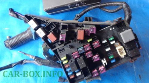
In the passenger compartment

Located on the driver's side, at the bottom of the dashboard, behind the plastic cover.
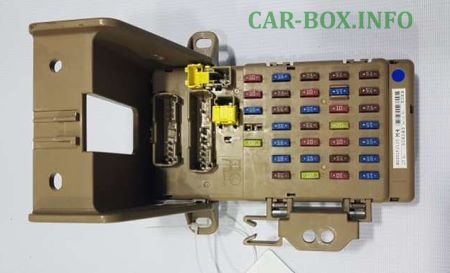
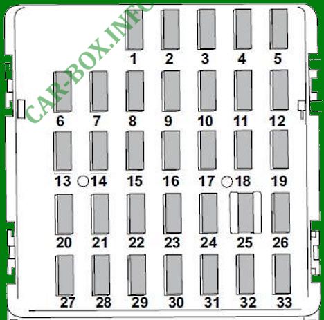
General view of the Subaru Forester SJ cabin fuse box.
| Diagram | ||
|---|---|---|
|
||
| No. | Decoding | A |
| 1 |
|
20 |
| 2 | Empty | - |
| 3 | Door locks drive | 15 |
| 4 | Windshield wiper blade defroster relay | 10 |
| 5 |
|
10 |
| 6 | Rearview mirror remote control drive | 7.5 |
| 7 | Central control unit | 15 |
| 8 | Stop lights | 15 |
| 9 | Windshield wiper blade defroster | 15 |
| 10 | Power supply (battery) | 7.5 |
| 11 | Turn signal control unit | 7.5 |
| 12 |
|
15 |
| 13 |
|
20 |
| 14 |
|
15 |
| 15 |
|
10 |
| 16 | Lighting | 7.5 |
| 17 | Heated seats | 15 |
| 18 | Reversing light | 10 |
| 19 | Daytime Running Lights | 7.5 |
| 20 | Socket for connecting auxiliary electrical equipment (in the instrument panel) | 10 |
| 21 |
|
7.5 |
| 22 |
|
10 |
| 23 | Not installed | - |
| 24 |
|
10 |
| 25 | Airbag system | 15 |
| 26 |
|
7.5 |
| 27 | Interior fan | 15 |
| 28 | 15 | |
| 29 | Fog lights | 15 |
| 30 | Empty | - |
| 31 |
|
7.5 |
| 32 | Clutch | 7.5 |
| 33 | ABS / VDC control unit | 7.5 |
| Back Side Relay | ||

|
||
| R1 | Ignition (IG 2) | |
| R2 | Accessory | |
It is also possible to place additional relay boards next to the main unit, their schemes are identical.
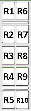
Description:
Unit No. 1
R1. Air flow, oxygen sensor;
R2. Electronic throttle control;
R3. Rear lamp and lighting;
R4. Power windows;
R5. Starter 1;
R6. Starter Cut (with push button start);
R7. Ignition IG1;
R8. Ignition IG2;
R9. Starter Cut (with push button start);
R10. Empty.
Unit #2
R1. Fuel pump (turbo);
R2.Self-closing;
R3. Main;
R4. Ignition (IG);
R5. Fuel pump (except Turbo);
R6. Empty;
R7. Seat heating;
R8. Wiper / De-icer;
R9. Empty;
R10. Front fog lamp.
