Compact crossovers have been produced since 2002 at a plant in California by a joint venture between General Motors and Toyota. On the platform of the Corolla model, two cars were created, differing in design, but technically identical. In this article, we will take a detailed look at the fuse box diagrams for the Toyota Matrix and Pontiac Vibe 1st generation (E130 body) 2002, 2003, 2004, 2005, 2006, 2007 release.
Here you will find the locations and photos of distribution boxes. Separately, we note the fuse responsible for the cigarette lighter and fuel pump relay.
In the engine compartment

It is located near the battery, on the left side of the engine compartment, behind a plastic cover.
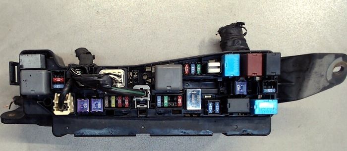
General view.
| Diagram | ||
|---|---|---|
|
||
| No. | Description | A |
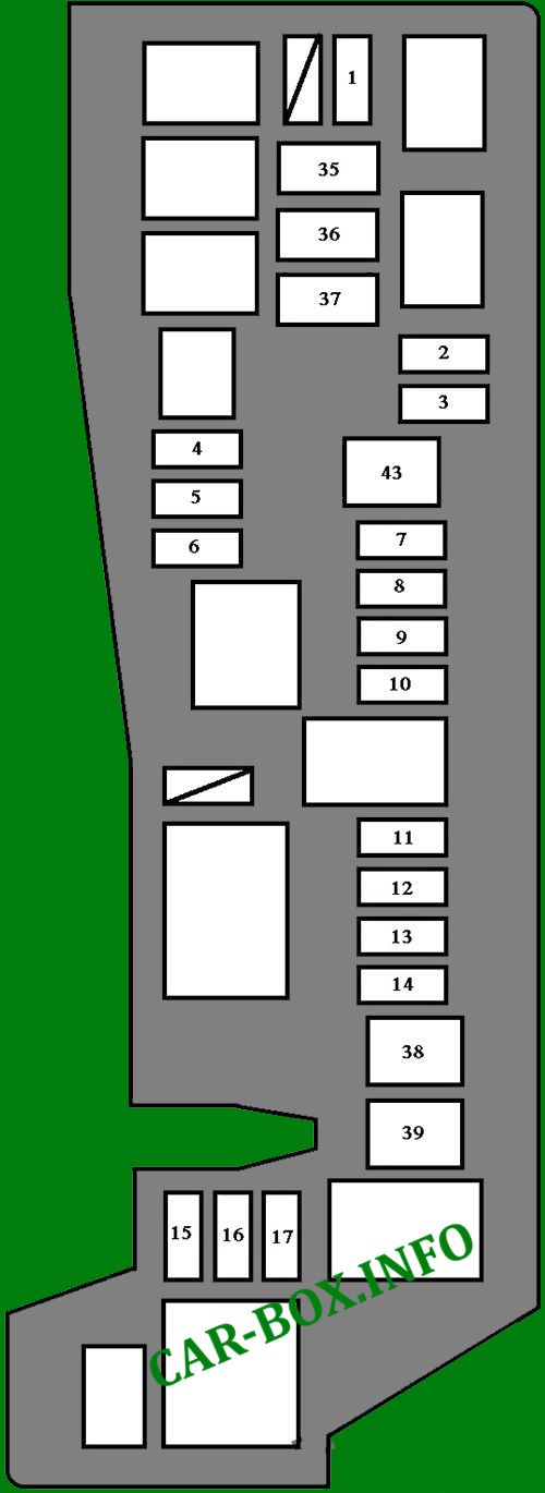
| 1 | Front fog lamps | 15 |
| 2 | Left healamp (high beam) | 10 |
| 3 | Right healamp (high beam), high beam warning lamp | 10 |
| 4 | Spare | 30 |
| 5 | 15 | |
| 6 | 10 | |
| 7 | Electronic throttle control system | 10 |
| 8 | Radio cassette | 30 |
| 9 | Starting system, fuse "AM2" | 30 |
| 10 | Car audio, clock, personal lamp, interior lamps, trunk lamp, open door warning lamps, wireless remote control system | 15 |
| 11 | Horn | 10 |
| 12 | Emergency flashers, direction indicators, turn signals | 10 |
| 13 | Multiport fuel injection system / sequential multiport fuel injection system, emission control system, EFI fuse | 15 |
| 14 | Charging system | 5 |
| 15 | Left headlamp (low beam) | 10 |
| 16 | Right headlamp (low beam) | 10 |
| 17 | Multiport fuel injection system / sequential multiport fuel injection system, emission control system | 15 |
| 35 | Anti-lock braking system ABS, vehicle stability control system, traction control system, auxiliary braking system | 30 |
| 36 | Cooling fan | 30 |
| 37 | Anti-lock braking system (without vehicle stabilization system) | 40 |
| Anti-lock braking system, vehicle stability control system, traction control system, auxiliary braking system (with vehicle stabilization system) | 50 | |
| 38 | Fuses "HEAD LH UPR", "HEAD RH UPR", "HEAD LH LWR" and "HEAD RH LWR" | 40 |
| 39 | Emission control system | 50 |
| 43 | Charging system, "ABS No. 1", "ABS No. 2", "RDI FAN", "FOG", "HTR", "AM1", "POWER", "DOOR", "ECU - B", "TAIL". "," STOP "," P / POINT "," INV "and" OBD ". | 100 |
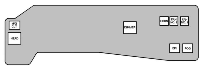
| Description of the relay modules | ||
|
||
| HEAD | Headlamps | |
| M / G | Air conditioning | |
| DIMMER | Headlights | |
| EFI | Injection system | |
| HORN | Sound Signal relay | |
| FAN | Cooling Fan | |
| FOG | Fog lamp | |
In the passenger compartment
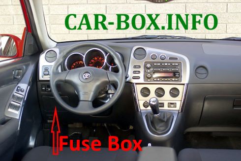
Located on the driver's side, below under the dashboard, behind a plastic cover.
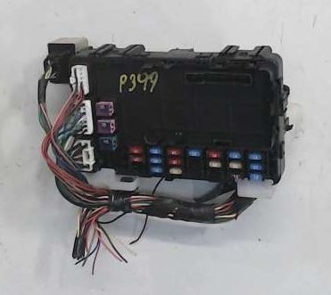
The photo shows an example.
| Assigment of fuses in the passenger compartment | ||
|---|---|---|

|
||
| No. | Appointment | A |
| 18 | Tail lamps, License Plate lamps, Instrument Panel lamps, Instrument Cluster lamps, Clock | 15 |
| 19 | On-board diagnostic system | 7.5 |
| 20 | Wipers | 25 |
| 21 | Charging system, multiport fuel injection system / sequential multiport fuel injection system, starting system, SRS airbag system | 15 |
| 22 | Brake lights, brake light high anti-lock braking system, shift lock control system, multiport fuel injection system / sequential multiport fuel injection system, cruise control system | 15 |
| 23 | Power door locking system, glass sunroof switch | 25 |
| 24 | Cigarette lighter fuse | 25 |
| 25 | Electric cooling fan, anti-lock braking system, traction control system, vehicle stabilization system, auxiliary braking system, shift lock control system, cruise control system | 10 |
| 26 | Rear window wiper | 15 |
| 27 | Air conditioning | 10 |
| 28 | Power outlet (115 VAC) | 15 |
| 29 | Power outlet (12V DC / in rear console box) | 15 |
| 30 | Daytime running lamps system | 10 |
| 31 | Powe outlet (dashboard), matrix cigarette lighter fuse, car audio, clock, power rearview mirror control, shift lock control system | 15 |
| 32 | Instruments and instruments, air conditioning, daytime running lights, charging system, automatic anti-glare interior rearview mirror, power windows, cruise control system, heated rear window, reversing lights, front passenger seat belt reminder lamp | 10 |
| 33 | Windshield washer, rear window washer | 15 |
| 34 | Engine management system | 10 |
| 40 | Air conditioning | 40 |
| 41 | Heated rear window, fuse "M-HTR / DEF I-UP" | 30 |
| 42 | Power windows, power sunroof | 30 |
| Rear side relay modules | ||

|
||
| A | Starter | |
| B | Heated rear window | |
| C | Vibe / Matrix fuel pump relay | |
| D | Power windows | |
| E | Ignition | |
