Table of Contents
Most of the power supply circuits of the electrical equipment of the Japanese hatchback are protected by fuses. Powerful current consumers are connected via relays. Protective elements are installed in distribution boxes located in the passenger compartment and under the hood.

In this article, we will take a detailed look at the fuse box diagrams for the Toyota Matrix E140 2nd generation 2008, 2009, 2010, 2011, 2012, 2013 model year.
In the engine compartment
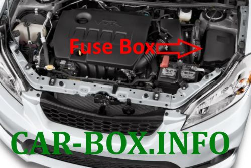
The distribution box is located on the left, near the battery.
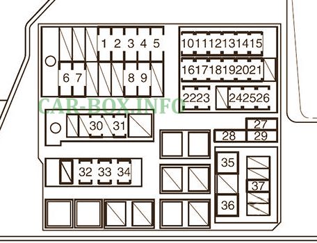
| Engine box fuse diagram |
|---|
|
| No. | Description | A |
| 1 | cooling fan | 30 |
| 2 | 40 | |
| 3 | Anti-lock braking system, vehicle stability control system | 30 |
| 4 | 50 | |
| 5 | Air conditioning | 50 |
| 6 | Charging system, RDI FAN, CDS FAN, ABS NO. 1, ABS NO. 3, INVERTER, HTR, HTR SUB NO. 1, HTR SUB NO. 3. ACC, CIG, METER, IGN, ECU-IG NO. 2, HTRIG, wiper, rear wiper, washer, ECU-IG NO. 1, AM1, 4WD, DOOR, STOP, FRONT DOOR, POWER, BACK DOOR, REAR DOOR, OBD, ACC-B, FRONT FOGGES, SUN ROOF, DEF, MIR HTR, REAR | 120 |
| 7 | Electric power steering | 60 |
| 8 | EFI MAIN, HORN, IG2 | 50 |
| 9 | headlamps | 50 |
| 10 | Emission control system | 10 |
| 11 | sequential multiport fuel injection system | 10 |
| 12 | Right headlamp (high beam) | 10 |
| 13 | Left headlamp (high beam) | 10 |
| 14 | RH headlamp (low beam), front fog lamps | 10 |
| 15 | Left headlamp (low beam) | 10 |
| 16 | sequential multiport fuel injection system | 10 |
| 17 | Direction indicators, emergency flashers | 10 |
| 18 | Charging system | 7.5 |
| 19 | sequential multiport fuel injection system | 7.5 |
| 20 | Starting system, sequential multiport fuel injection system | 30 |
| 21 | Spare | 20 |
| 22 | Launch system | 7.5 |
| 23 | Engine immobilizer system | 10 |
| 24 | Main body ECU, sensor and meters, daytime running light system, air conditioning system, wireless remote control | 10 |
| 25 | Audio system | 15 |
| 26 | Indoor lighting, personal lighting, watches | 10 |
| 27 | Spare | 10 |
| 28 | 30 | |
| 29 | 20 | |
| 30 | Audio system | 30 |
| 31 | Spare | 10 |
| 32 | sequential multiport fuel injection system, EFI NO. 1, EFI NO. 2 | 20 |
| 33 | Horn | 10 |
| 34 | Multiport fuel injection system / sequential multiport fuel injection system, starting system, IGN, METER | 15 |
| 35 | PTC heater | 30 |
| 36 | 30 | |
| 37 | AC INVERTER | 15 |
In the passenger compartment
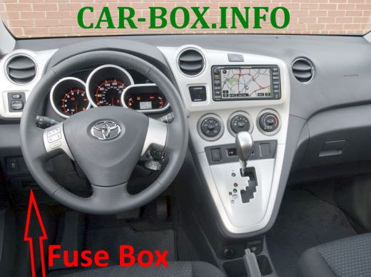
The fuse box is located on the driver's side, below the dashboard, behind a plastic cover.
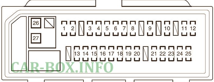
| Assigment of fuses in the passenger compartment | ||
|---|---|---|
|
||
| No. | Decoding | A |
| 1 | Parking lamps, tail lamps, license plate lamps, multiport fuel injection system / sequential multiport fuel injection system, instrument cluster lamps | 10 |
| 2 | Switch illumination | 7.5 |
| 3 | Power windows | 20 |
| 4 | 20 | |
| 5 | 20 | |
| 6 | Roof hatch | 20 |
| 7 | Cigarette lighter fuse Matrix, socket | 15 |
| 8 | Exterior mirrors, audio system, main body ECU, clock, shift lock control system | 7.5 |
| 9 | Spare | 7.5 |
| 10 | 15 | |
| 11 | SRS airbag system, multiport fuel injection system / sequential multiport fuel injection system, front passenger classification system | 7.5 |
| 12 | Gauge and Meters | 7.5 |
| 13 | Air conditioning system, heated rear window | 10 |
| 14 | Wipers | 25 |
| 15 | Rear window wiper | 15 |
| 16 | Windshield washer | 15 |
| 17 | Main body ECU, electric power steering, electric cooling fan (s), shift lock control system, anti-lock braking system, multiport fuel injection system / sequential multiport fuel injection system, tire pressure warning system, vehicle stability control system | 10 |
| 18 | Reversing lamps, charging system, rear window defogger | 10 |
| 19 | On-board diagnostic system | 7.5 |
| 20 | Brake lights, high set brake light, anti-lock braking system, vehicle stability control system, multiport fuel injection system / sequential multiport fuel injection system, shift lock control system | 10 |
| 21 | Electric door locking system | 25 |
| 22 | CIG, ACC | 25 |
| 24 | All-wheel drive system | 7.5 |
| 25 | Starting system, shift lock control system, ACC, CIG | 7.5 |
| 26 | Heated rear window, MIR HTR, multiport fuel injection system / sequential multiport fuel injection system | 30 |
| 27 | Power windows | 30 |
