A minivan with a 5-size body, three rows of seats in a 7-seater saloon went on sale in the fall of 2004. The car is considered a continuation of the Gaia lineup, although the characteristics of the two cars differ. While the Gaia shares a chassis with the Ipsum, the Isis has a different, multidisciplinary focus, and is more similar to the Noah and Voxy models. In this article, we will take a detailed look at the fuse box diagrams for the Toyota Isis 1st generation (XM10): 2004, 2005, 2006, 2007, 2008, 2009, 2010, 2011, 2012, 2013, 2014, 2015, 2016 and 2017.

Here you will find the locations and photos of the blocks. The fuse responsible for the “Cigarette lighter” is highlighted in bold.
In the engine compartment

The distribution boxes are located near the battery.
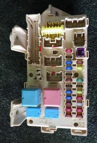
Type 1

Photo - an example of the execution of the main fuse box.
| Diagram | ||
|---|---|---|
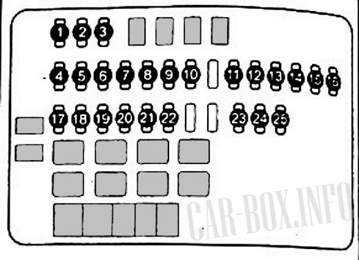
|
||
| No. | Description | A |
| 1 | Connector for additional equipment, 12 V socket - ACC-B | 25 |
| 2 | DOOR - Central locking | 25 |
| 3 | Rear heater / air conditioner RR HTR | 15 |
| 4 | AM2 - Engine start switch | 7.5 |
| 5 | ECU-B2 - System "Entry & Start" | 10 |
| 6 | ETCS engine management system | 10 |
| 7 | TURN - HAZ - Direction indicators | 10 |
| 8 | HORN - Sound signal | 10 |
| 9 | IG2 - Engine management system | 15 |
| 10 | IGT / INJ - Engine management system | 15 |
| 11 | STR LOCK - Steering lock system | 20 |
| 12 | Engine management system - EFI MAIN | 20 |
| 13 | DOOR 2 - Central locking | 25 |
| 14 | PBD - Electric rear door | 30 |
| 15 | SHORT | |
| 16 | AM2 - Engine start switch | 30 |
| 17 | PSD RD - Electric sliding door drive (right) | 30 |
| 18 | PSD LD - Electric sliding door drive (left) | 30 |
| 19 | H-LH RH - Headlamp (right) | 15 |
| 20 | H-LP LH - Headlamp (left) | 15 |
| 21 | EFI 1 & 2 - Engine Management System | 10 |
| 22 | 10 | |
| 23 | ECU - B - Instrument Cluster, Engine Management System | 10 |
| 24 | DOME - Interior and Trunk Lighting | 10 |
| 25 | RAD1 - Stereo, radio | 20 |
Type 2
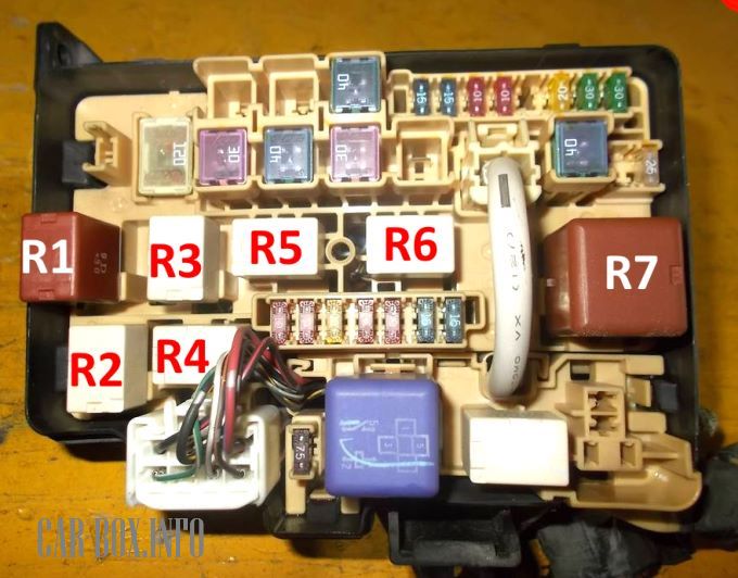
Photo with the designation of the relay modules.
| Diagram | |
|---|---|
|
|
| No. | Appointment |
| 1 | Starter |
| 2 | Electric sliding door (right) - PSD RH |
| 3 | Electric sliding door (left) - PSD LH |
| 4 | Right headlamp - H-LP RH |
| 5 | Left headlamp - H-LP LH |
| 6 | Instrument cluster, electronic engine control unit - ECU-B |
| 7 | Interior and luggage compartment lighting - DOME |
| 8 | Radio tape recorder - RAD1 |
| 9 | Anti-lock braking system (ABS) |
| 10 | Rear Heater / Air Conditioning - RR HTR |
| 11 | Empty |
| 12 | Ignition lock - AM2 |
| 13 | Power tailgate - PBD |
| 14 | Electronic engine control unit - EFI |
| 15 | Electronic engine control unit - EFI2 |
| 16 | Sound signal - HORN |
| 17 | Direction indicators - TRN HAZARD |
| 18 | (Models with dv. 112-PE) Generator - ALT-S |
| (Models with dv. 1A1-PZE) Electronic engine control unit - ETCS | |
| R1 | cooling fan relay |
| R2 | cooling fan relay |
| R3 | Signal |
| R4 | cooling Fan |
| R5 | Engine management |
| R6 | Engine management |
In the additional block there are fuses responsible for the low and high beam headlights (15A), and for the all-wheel drive system for 10A SCL - ABS / 4WD.
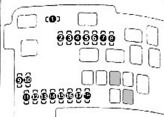
In the passenger compartment
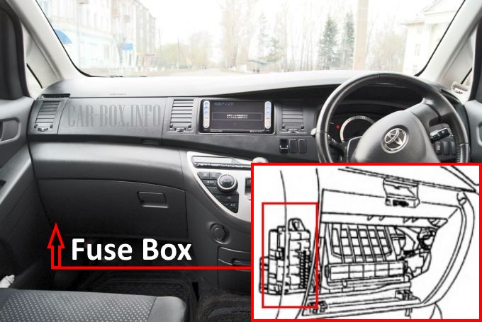
Located on the passenger side behind the glove compartment.
The photo shows an example.
| Assigment of fuses in the passenger compartment | ||
|---|---|---|

|
||
| No. | Description | A |
| IGN | Ignition system | 10 |
| TAIL1 | Rear marker lamps | 15 |
| FR FOG | Fog lamps | 15 |
| AM1 | Egnition lock | 25 |
| TAIL2 | Parking lamps | 7 |
| RR WIPER | Rear door glass cleaner | 15 |
| P-POINT | Toyota Isis cigarette lighter fuse, Additional equipment socket | 15 |
| A / C | Air conditioning | 15 |
| ACC | Radio cassette | 7.5 |
| TAIL3 | Parking lamps | 7.5 |
| FR DEF | Windshield defroster | 20 |
| RR P / W | Electric rear power windows | 30 |
| DOOR | central locking | 25 |
| WIPER | Windshield wiper | 20 |
| ECU-IG | ABS system | 10 |
| RR DEF | Rear door glass heater | 25 |
| GAUGE | Instrument cluster, reversing lamps | 10 |
| STOP | Stop lamps | 7.5 |
| Purpose of relay modules | ||
| R1 | Heater | |
| R2 | IGN | |
| R3 | Heated rear window | |
| R4 | Tail lamps | |
